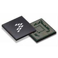
SC900841JVK Freescale Semiconductor, SC900841JVK Datasheet - Page 147

SC900841JVK
Manufacturer Part Number
SC900841JVK
Description
IC POWER MGT 338-MAPBGA
Manufacturer
Freescale Semiconductor
Specifications of SC900841JVK
Applications
PC's, PDA's
Operating Temperature
-40°C ~ 85°C
Mounting Type
Surface Mount
Package / Case
338-TBGA
Input Voltage
2.8 V to 4.4 V
Maximum Operating Temperature
+ 85 C
Minimum Operating Temperature
- 40 C
Lead Free Status / RoHS Status
Lead free / RoHS Compliant
Current - Supply
-
Voltage - Supply
-
Lead Free Status / Rohs Status
Lead free / RoHS Compliant
Available stocks
Company
Part Number
Manufacturer
Quantity
Price
Company:
Part Number:
SC900841JVK
Manufacturer:
Freescale Semiconductor
Quantity:
10 000
Company:
Part Number:
SC900841JVKR2
Manufacturer:
Freescale Semiconductor
Quantity:
10 000
- Current page: 147 of 192
- Download datasheet (8Mb)
accessory plug to the 900841 audio pins.
between a headphone, a headset (cellular headset
with a microphone), and push-to-talk (PPT) button
switch press:
HPDET
• If MIC2BIAS = 0 : Accessory Attached
• If MIC2BIAS = 1 : Headphone Inserted/Removed
HSDET = Headset Inserted/Removed
• Detect current drawing in MC2B pin when headset is
• Interrupt mask bit: MHSDET (1=masked,
SWMPINT = Momentary Button Press
• Detect a short button press of < 2.0 s in headset
• Interrupt is set after the button is released
• Interrupt mask bit: MSWMPINT (1=masked,
Analog Integrated Circuit Device Data
Freescale Semiconductor
2.2Kohms
MIC
Figure 73
There are four audio interrupts to distinguish
• Detect a 0.4 V threshold in MC2IN when a headphone
• Interrupt mask bit: MHPDET (1=masked, 0=unmasked)
inserted/removed
0=unmasked)
button.
0=unmasked)
is inserted / removed
Stereo Headphone Plug
G
Stereo Headset Plug
show the connection of an audio
G
R
M
L
R
L
Figure 73. Connection of Audio Accessory Plug to SC900841 Pins
R
L
R
L
G = GROUND
M = MIC
R = RIGHT CHANNEL
L = LEFT CHANNEL
Jack
G
M
R
L
JACKM
SWLPINT = Long Button Press
• Detect a long button press of > 2.0 s in headset
• Interrupt is set after the button is released
• Interrupt mask bit: MSWLPINT (1=masked,
will trigger the Level 1 AUX interrupt (MAUX interrupt mask).
All the above interrupts must be unmasked (by writing ‘0’ to
its respective interrupt mask) to be enabled. A SPI read will
clear these interrupts and allow the detection of a following
interrupt.
interrupts are used for insertion and removal of an audio
accessory. For example, if a headset is inserted to the audio
jack, a HPDET interrupt will be set and that will trigger the
AUX interrupt. After the firmware does a SPI read both
HPDET and AUX these bits will be automatically cleared
(‘0’) by the PMIC . If the headphone is removed from the jack,
HPDET will be set again to indicate that the headphone was
removed.
flowchart in
to process and to enable these audio interrupts.
to ‘1’ to enable the audio accessory detection circuit. All
external jack inputs are debounced by 30 Lms.
Rb
button
0=unmasked)
These four interrupts are Level 2 interrupts that when set
It is important to point out that HSDET and HPDET
The sequence of events below explains the
HSDETEN and AUDIOFF spi bits must be both set
2.2K
0.22UF
Figure 74
MC2B
MC2IN
GND
HSR
HSL
should be followed by software
FUNCTIONAL DEVICE OPERATION
PMIC
PMICINT
TO LANGWELL
SCU
AUDIO
900841
147
Related parts for SC900841JVK
Image
Part Number
Description
Manufacturer
Datasheet
Request
R
Part Number:
Description:
Manufacturer:
Freescale Semiconductor, Inc
Datasheet:
Part Number:
Description:
Manufacturer:
Freescale Semiconductor, Inc
Datasheet:
Part Number:
Description:
Manufacturer:
Freescale Semiconductor, Inc
Datasheet:
Part Number:
Description:
Manufacturer:
Freescale Semiconductor, Inc
Datasheet:
Part Number:
Description:
Manufacturer:
Freescale Semiconductor, Inc
Datasheet:
Part Number:
Description:
Manufacturer:
Freescale Semiconductor, Inc
Datasheet:
Part Number:
Description:
Manufacturer:
Freescale Semiconductor, Inc
Datasheet:
Part Number:
Description:
Manufacturer:
Freescale Semiconductor, Inc
Datasheet:
Part Number:
Description:
Manufacturer:
Freescale Semiconductor, Inc
Datasheet:
Part Number:
Description:
Manufacturer:
Freescale Semiconductor, Inc
Datasheet:
Part Number:
Description:
Manufacturer:
Freescale Semiconductor, Inc
Datasheet:
Part Number:
Description:
Manufacturer:
Freescale Semiconductor, Inc
Datasheet:
Part Number:
Description:
Manufacturer:
Freescale Semiconductor, Inc
Datasheet:
Part Number:
Description:
Manufacturer:
Freescale Semiconductor, Inc
Datasheet:
Part Number:
Description:
Manufacturer:
Freescale Semiconductor, Inc
Datasheet:


