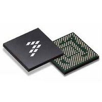
SC900841JVK Freescale Semiconductor, SC900841JVK Datasheet - Page 57

SC900841JVK
Manufacturer Part Number
SC900841JVK
Description
IC POWER MGT 338-MAPBGA
Manufacturer
Freescale Semiconductor
Specifications of SC900841JVK
Applications
PC's, PDA's
Operating Temperature
-40°C ~ 85°C
Mounting Type
Surface Mount
Package / Case
338-TBGA
Input Voltage
2.8 V to 4.4 V
Maximum Operating Temperature
+ 85 C
Minimum Operating Temperature
- 40 C
Lead Free Status / RoHS Status
Lead free / RoHS Compliant
Current - Supply
-
Voltage - Supply
-
Lead Free Status / Rohs Status
Lead free / RoHS Compliant
Available stocks
Company
Part Number
Manufacturer
Quantity
Price
Company:
Part Number:
SC900841JVK
Manufacturer:
Freescale Semiconductor
Quantity:
10 000
Company:
Part Number:
SC900841JVKR2
Manufacturer:
Freescale Semiconductor
Quantity:
10 000
- Current page: 57 of 192
- Download datasheet (8Mb)
Update-Ended Interrupt
which indicates that there is over 999 ms available to read
valid time and date information.
RTC Timer Calibration
is limited to the performance of the 32.768 kHz crystal input.
For clock accuracy beyond the limits of the crystal oscillator,
a calibration circuit is included. The processor can use a high-
frequency clock to sample the 32.768 kHz output to
determine if it is fast or slow, and calculate an adjustment
value. The adjustment algorithm has a resolution of ±477
nanoseconds-per-second average adjustment, which
equates to a time accuracy of approximately 1.2 seconds per
month.
Table 24. RTC Date/Time Configuration Register Structure and Bits Description
Analog Integrated Circuit Device Data
Freescale Semiconductor
HRSALARM
SECALARM
MINALARM
If enabled, an interrupt occurs after every update cycle
By default, the calibration circuit is off and clock accuracy
Reserved
Reserved
Reserved
Reserved
Reserved
Reserved
PA-HA
Name
PA-H
SEC
HRS
MIN
CLOCK GENERATION AND REAL TIME CLOCK (RTC) REGISTERS AND BITS DESCRIPTION
Bits
6:0
6:0
6:0
6:0
5:0
5:0
7
7
7
7
6
7
6
7
Seconds Counter Register
Reserved
Seconds Alarm Setting Register
Reserved
Minutes Counter Register
Reserved
Minutes Alarm Setting Register
Reserved
Hours Counter Register
Fixed to 0
AM/PM Indication, Only active during 12 Hr mode
Hours Alarm Setting Register
Fixed to 0
AM/PM Alarm Setting, Only active during 12 Hr mode
x0 = AM
x1 = PM
x0 = AM
x1 = PM
RTCMA (ADDR 0x13 - R/W - Default Value: 0x00)
RTCSA (ADDR 0x11 - R/W - Default Value: 0x00)
RTCHA (ADDR 0x15 - R/W - Default value: 0x00)
RTCM1 (ADDR 0x12 -R/W - Default Value: 0x00)
RTCH (ADDR 0x14 - R/W - Default Value: 0x00)
RTCS (ADDR 0x10 - R/W - Default Value: 0x00)
the ADJ register. A "0" in the ADJ bit turns calibration off. The
Sign bit in the Trim register determines if periodic
adjustments are made to speed up or slow down the clock.
grow or shrink the average 1.0 Hz clock period. By default,
one second is defined as 32,768 periods of the CLK32K input
pin. Each period of the input clock is approximately 30.5 μs.
By occasionally adding (or subtracting) one extra cycle per
second, the average second can be adjusted. If SIGN is high
(subtract one), occasional seconds will be trimmed to 32,767
cycles. If SIGN is low (add one), occasional seconds will be
trimmed to 32,769 cycles.
number of seconds to adjust out of every 64 seconds, and
can range from 0-63. For example, TRIMVAL = 0x08 then 8
seconds out of every 64 will be adjusted up or down,
according to the SIGN bit.
Calibration can be turned on by setting the RTC ADJ bit of
When calibration is enabled, the Trim register is used to
The 6-bit TRIMVAL in the Trim register represents the
Description
CLOCK GENERATION AND REAL TIME CLOCK (RTC)
FUNCTIONAL DEVICE OPERATION
900841
57
Related parts for SC900841JVK
Image
Part Number
Description
Manufacturer
Datasheet
Request
R
Part Number:
Description:
Manufacturer:
Freescale Semiconductor, Inc
Datasheet:
Part Number:
Description:
Manufacturer:
Freescale Semiconductor, Inc
Datasheet:
Part Number:
Description:
Manufacturer:
Freescale Semiconductor, Inc
Datasheet:
Part Number:
Description:
Manufacturer:
Freescale Semiconductor, Inc
Datasheet:
Part Number:
Description:
Manufacturer:
Freescale Semiconductor, Inc
Datasheet:
Part Number:
Description:
Manufacturer:
Freescale Semiconductor, Inc
Datasheet:
Part Number:
Description:
Manufacturer:
Freescale Semiconductor, Inc
Datasheet:
Part Number:
Description:
Manufacturer:
Freescale Semiconductor, Inc
Datasheet:
Part Number:
Description:
Manufacturer:
Freescale Semiconductor, Inc
Datasheet:
Part Number:
Description:
Manufacturer:
Freescale Semiconductor, Inc
Datasheet:
Part Number:
Description:
Manufacturer:
Freescale Semiconductor, Inc
Datasheet:
Part Number:
Description:
Manufacturer:
Freescale Semiconductor, Inc
Datasheet:
Part Number:
Description:
Manufacturer:
Freescale Semiconductor, Inc
Datasheet:
Part Number:
Description:
Manufacturer:
Freescale Semiconductor, Inc
Datasheet:
Part Number:
Description:
Manufacturer:
Freescale Semiconductor, Inc
Datasheet:


