56-U04-E01 Spectrum Control, 56-U04-E01 Datasheet - Page 120
56-U04-E01
Manufacturer Part Number
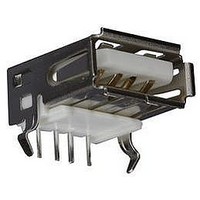
56-U04-E01
Description
USB CONNECTOR, RECEPTACLE, 4POS, THD
Manufacturer
Spectrum Control
Series
USB-Er
Datasheet
1.56-U04-E01.pdf
(258 pages)
Specifications of 56-U04-E01
Connector Type
USB
No. Of Contacts
4
Contact Termination
Right Angle Through Hole
Connector Mounting
PCB
Gender
Receptacle
Contact Plating
Gold
Product
USB Type A Connectors
Standard
USB
Number Of Ports
1
Features
Spectrum USB Filtered Connectors TYPE A R/A USB .05pF 5A 10VDC
Insulation Resistance
10 MOhms
Mounting Angle
Right
Number Of Positions / Contacts
4
Lead Free Status / RoHS Status
Contains lead / RoHS non-compliant
Lead Free Status / RoHS Status
Contains lead / RoHS non-compliant


120
Filter Selection
EMI Filter Performance
The electrical characteristics table and insertion loss
graphs indicate the performance of feed-thru capacitors
and Pi type filters. Utilize this information to specify the
EMI filtering components included in your filter plate.
Custom Filtering
Spectrum Control filter plates are engineered to
accommodate selective line filtering. Several different
types of filters may be specified in a single, easy to
install filter plate, allowing you to facilitate a wide range
of filtering requirements.
the filters and positions required. The example below
represents a 10 pin, 2 row plate with six 1000 pF feed-
thru capacitors and four 1700 pF Pi type filters.
Part Number
Based on front
view of plate
* 3 dB cut-off frequency calculated at the maximum capacitance.
** For Hi-Density centers (2 mm) only C style filters are available, to a maximum of 4000pF.
SPECTRUM CONTROL INC. • 8031 Avonia Rd. • Fairview, PA 16415 • Phone: 814-474-2207 • Fax: 814-474-2208 • Web site: www.spectrumcontrol.com
SPECTRUM CONTROL GmbH • Hansastrasse 6 • 91126 Schwabach, Germany • Phone: (49)-9122-795-0 • Fax: (49)-9122-795-58
Designation
Filter
For selective line filtering, provide a sketch indicating
M
A
B
C
D
E
G
H
K
N
O
P
Q
R
S
F
J
L
T
I
Grounded
Insulated
Circuits
Filter**
Insert
Pi
C
10
1
F
F
1000 pF
1500 pF
2500 pF
4000 pF
1000 pF
1700 pF
2500 pF
5000 pF
100 pF
135 pF
470 pF
820 pF
100 pF
135 pF
470 pF
820 pF
Value
68 pF
10 pF
68 pF
F
F
Capacitance
F
F
Tolerance
+100/-0%
+100/-0%
+100/-0%
+100/-0%
+100/-0%
+100/-0%
+100/-0%
±20%
±20%
±20%
±20%
±20%
±20%
±20%
±20%
±20%
±20%
±20%
Max.
R
R
Frequency
3 dB Max
Cut-off
(MHz)*
R
R
635
3.5
1.3
1.9
1.3
77
53
23
11
65
46
25
11
.8
.7
6
5
6
5
6
5
Voltage DC
Working
-55°C to
+125°C
100V
100V
100V
100V
100V
100V
100V
100V
100V
100V
100V
100V
100V
100V
100V
100V
100V
100V
50V
100
100
80
40
20
60
80
40
20
60
0
0
0.1MHz
0.1MHz
Typical Insertion Loss
Above curves represent application of proper
grounding fundamentals, for assistance consult
with Spectrum Control.
MHz
—
—
—
—
—
—
—
—
—
—
—
—
—
—
5
1
5
9
1
4
9
C-Style Capacitor
Pi Capacitor
1MHz
1MHz
50 ohm system per MIL-STD-220 (no load)
MHz
Minimum Insertion Loss - Decibels (dB)
10
—
—
—
—
11
15
—
—
—
—
—
—
—
15
2
3
4
2
6
9
MHz
20
—
—
—
10
17
21
—
—
—
—
—
—
14
16
28
2
6
7
4
7
10MHz
10MHz
Frequency
Frequency
MHz
12
14
16
23
27
13
16
28
28
41
50
—
—
—
—
—
—
1
7
1
9
Q
100MHz
100MHz
F
R
All High-Density capacitors
are 50 volts @ 125°C.
MHz
100
G
13
18
20
22
29
34
18
23
24
35
41
53
S
—
—
—
1
5
1
2
6
H
T
I
MHz
200
10
19
24
26
29
35
38
17
22
31
36
49
54
66
—
—
1GHz)
1GHz
3
6
6
9
E
P
D
O
MHz
500
10
14
16
25
30
32
36
38
42
17
22
26
36
45
51
64
70
70
C
—
—
N
M
B
10GHz
10GHz
L
A
GHz
16
19
20
27
33
35
37
40
46
23
28
34
43
52
59
69
70
70
—
—
1
Related parts for 56-U04-E01
Image
Part Number
Description
Manufacturer
Datasheet
Request
R

Part Number:
Description:
USB CONNECTOR, RECEPTACLE, 4POS, THD
Manufacturer:
Spectrum Control
Datasheet:
Part Number:
Description:
USB CONNECTOR, RECEPTACLE, 4POS, THD
Manufacturer:
Spectrum Control
Datasheet:
Part Number:
Description:
USB CONNECTOR, RECEPTACLE, 4POS, THD
Manufacturer:
Spectrum Control
Datasheet:

Part Number:
Description:
EMI/RFI Suppressors & Ferrites 15 POS CUSTOM MATE U
Manufacturer:
Spectrum Control

Part Number:
Description:
Power Line Filters Single Stage
Manufacturer:
Spectrum Control Inc.
Datasheet:
Part Number:
Description:
High Current Single Line Feed-thru Filters
Manufacturer:
Spectrum Control Inc.
Datasheet:
Part Number:
Description:
Switched And Fused Filtered Power Entry Modules
Manufacturer:
Spectrum Control Inc.
Datasheet:
Part Number:
Description:
Surface Mount Emi Filters
Manufacturer:
Spectrum Control Inc.
Datasheet:
Part Number:
Description:
(PSMx Series) Surface Mount EMI Filters
Manufacturer:
Spectrum Control
Datasheet: