56-U04-E01 Spectrum Control, 56-U04-E01 Datasheet - Page 16
56-U04-E01
Manufacturer Part Number
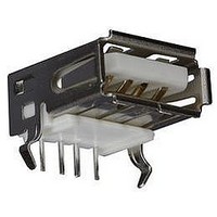
56-U04-E01
Description
USB CONNECTOR, RECEPTACLE, 4POS, THD
Manufacturer
Spectrum Control
Series
USB-Er
Datasheet
1.56-U04-E01.pdf
(258 pages)
Specifications of 56-U04-E01
Connector Type
USB
No. Of Contacts
4
Contact Termination
Right Angle Through Hole
Connector Mounting
PCB
Gender
Receptacle
Contact Plating
Gold
Product
USB Type A Connectors
Standard
USB
Number Of Ports
1
Features
Spectrum USB Filtered Connectors TYPE A R/A USB .05pF 5A 10VDC
Insulation Resistance
10 MOhms
Mounting Angle
Right
Number Of Positions / Contacts
4
Lead Free Status / RoHS Status
Contains lead / RoHS non-compliant
Lead Free Status / RoHS Status
Contains lead / RoHS non-compliant


16
Note: For 5/8-24 and 7/16-28 please refer to the specific instruction noted on part drawings or see page 84 of the catalog.
Filter Installation
Threaded Style Filters
s
s
s
Solder-in Style Filters
s
s
s
s
s
SPECTRUM CONTROL INC. • 8031 Avonia Rd. • Fairview, PA 16415 • Phone: 814-474-2207 • Fax: 814-474-2208 • Web site: www.spectrumcontrol.com
SPECTRUM CONTROL GmbH • Hansastrasse 6 • 91126 Schwabach, Germany • Phone: (49)-9122-795-0 • Fax: (49)-9122-795-58
Exceeding recommended mounting torque may
result in damage to the capacitor within the filter
due to possible twisting or elongation of the case.
For product without hex surfaces do not hold the
filter with pliers or other gripping tools. Pressure
exerted on the filter case may crack the ceramic
capacitor element.
Proper use of filters requires that the filter case be
adequately grounded to form an effective path for
the interference.
A controlled temperature profile not exceeding
6°F (3°C) per second is recommended when
soldering filters.
When soldering to terminals of a filter, a heat sink
should always be used adjacent to the body of
the filter.
60-40 solder is recommended for installation of
the filter into the chassis as well as soldering to the
terminals. If a filter style without an eyelet is being
soldered into a chassis, iron processes should be
avoided and the recommended solder alloy is
60-38-2.
Installation hole size for a solder-in filter should
be 0.003-0.005" over the maximum tolerance of
the minor diameter of the mounting portion of the
eyelet with a ±0.002" tolerance.
Machine/oven soldering 385-415°F (195-210°C)
using a dwell and cycle time fast enough to reflow
the solder and ramped to maintain less than
6°F/sec rate of change.
5/16-24 *
Thread
1/4-28 *
5/16-32
3/8-32
Filter
10-32
12-28
12-32
Size
4-40
6-40
6-32
8-32
Maximum Mounting Torque
in-lbs
1.5
3
3
4
4
6
6
7
7
7
9
0.170
0.339
0.339
0.452
0.452
0.678
0.678
0.791
0.791
0.791
1.017
Nm
0.120
0.147
0.147
0.173
0.190
0.228
0.228
0.261
0.323
0.323
0.386
(in)
Mounting Hole Dia.
* Recommended mounting
s
Soldering to Filter Terminals
s
s
s
s
s
s
s
hole size for threads with flats
1/4-28 with .200
(5.08) Flats
For iron soldering to filter body, preheat compo-
nents at 250-300°F (120-150°C), solder iron is
recommended to be set at 500-550°F (260-290°C).
The dwell on the solder joint should be less than 5
seconds.The time is dependent on the heat sinking
provided by the chassis so a longer preheat may
be required.
Use a temperature controlled soldering iron with
tip temperature of 525 ± 10°F (275 ± 5°C).
Use an SN 63 RMA flux core solder.
Make mechanical wire connection.
Use heat sink next to filter body where possible.
Clean soldering iron tip.
Clip end of solder (remove 0.5") to expose flux
for soldering.
Apply soldering iron to wire/flag junction at wetted
solder tip region of iron (Wetted Bridge Method).
Immediately apply solder. Dwell time for soldering
iron tip on product should be 3-5 seconds maximum.
(6.60 ± .076)
.260 ± .003
(mm)
3.05
3.73
3.73
4.39
4.83
5.79
5.79
6.63
8.20
8.20
9.80
(5.33 ± .076)
.210 ± .003
English
# 31
# 26
# 26
# 17
# G
# W
# P
# P
# 8
# 1
# 1
Dimensions in inches (mm)
5/16-24 with .250
(6.35) Flats
(8.13 ± .076)
.320 ± .003
Drill Size
Metric (mm)
(6.60 ± .076)
.260 ± .003
3.10
3.75
3.75
4.40
5.10
5.80
5.80
6.70
8.25
8.25
9.90
Related parts for 56-U04-E01
Image
Part Number
Description
Manufacturer
Datasheet
Request
R

Part Number:
Description:
USB CONNECTOR, RECEPTACLE, 4POS, THD
Manufacturer:
Spectrum Control
Datasheet:
Part Number:
Description:
USB CONNECTOR, RECEPTACLE, 4POS, THD
Manufacturer:
Spectrum Control
Datasheet:
Part Number:
Description:
USB CONNECTOR, RECEPTACLE, 4POS, THD
Manufacturer:
Spectrum Control
Datasheet:

Part Number:
Description:
EMI/RFI Suppressors & Ferrites 15 POS CUSTOM MATE U
Manufacturer:
Spectrum Control

Part Number:
Description:
Power Line Filters Single Stage
Manufacturer:
Spectrum Control Inc.
Datasheet:
Part Number:
Description:
High Current Single Line Feed-thru Filters
Manufacturer:
Spectrum Control Inc.
Datasheet:
Part Number:
Description:
Switched And Fused Filtered Power Entry Modules
Manufacturer:
Spectrum Control Inc.
Datasheet:
Part Number:
Description:
Surface Mount Emi Filters
Manufacturer:
Spectrum Control Inc.
Datasheet:
Part Number:
Description:
(PSMx Series) Surface Mount EMI Filters
Manufacturer:
Spectrum Control
Datasheet: