56-U04-E01 Spectrum Control, 56-U04-E01 Datasheet - Page 232
56-U04-E01
Manufacturer Part Number
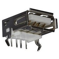
56-U04-E01
Description
USB CONNECTOR, RECEPTACLE, 4POS, THD
Manufacturer
Spectrum Control
Series
USB-Er
Datasheet
1.56-U04-E01.pdf
(258 pages)
Specifications of 56-U04-E01
Connector Type
USB
No. Of Contacts
4
Contact Termination
Right Angle Through Hole
Connector Mounting
PCB
Gender
Receptacle
Contact Plating
Gold
Product
USB Type A Connectors
Standard
USB
Number Of Ports
1
Features
Spectrum USB Filtered Connectors TYPE A R/A USB .05pF 5A 10VDC
Insulation Resistance
10 MOhms
Mounting Angle
Right
Number Of Positions / Contacts
4
Lead Free Status / RoHS Status
Contains lead / RoHS non-compliant
Lead Free Status / RoHS Status
Contains lead / RoHS non-compliant


232
Quality Acceptance Test Specifications
All filtered connectors undergo extensive testing
to assure that all product meets our high quality
expectations. Many of the tests are performed 100%
as routine and others are carried out on a sample
basis when this is deemed more meaningful.
Visual
The connectors shall be manufactured and processed
in a careful and workmanlike manner in accordance
with good design and sound practice. All connectors
shall be checked 100% to insure dimensions are as
shown in this catalog.
Capacitance
Checked on 100% of the contacts per detailed
specifications when measured @ 25°C, 1 KHz, 0.1 to
1.0VRMS. On insulated feed-thru lines, the maximum
capacitance is 25 pF.
Dissipation factor
4% maximum, checked 100% @ 25°C, 1KHz, 0.1 to
1.0VRMS
Dielectric withstanding voltage
Performed on 100% of the filtered contacts. The test
voltage unless otherwise specified will be 2.5 times
the working voltage as specified at 25°C. This voltage
will be applied for 1 to 5 seconds with the charging
current limited to 50 milliamps.
Insulation resistance
Performed on 100% of the filtered contacts at
25°C. The minimum acceptance level will be 1000
megohms at 25°C and 100 megohms at 125°C if
required. This test will be carried out in accordance
with MIL-STD-202 Method 302, test voltage of
100VDC or at rated voltage whichever is less.
Environmental Performance
* All tests are performed per applicable MIL spec.
SPECTRUM CONTROL INC. • 8031 Avonia Rd. • Fairview, PA 16415 • Phone: 814-474-2207 • Fax: 814-474-2208 • Web site: www.spectrumcontrol.com
SPECTRUM CONTROL GmbH • Hansastrasse 6 • 91126 Schwabach, Germany • Phone: (49)-9122-795-0 • Fax: (49)-9122-795-58
Test*
Description
Vibration
Thermal Shock
Immersion
Salt Spray
Moisture Resistance
Shock
Barometric Pressure
Resistance to Solder Heat
Terminal Strength
Contact Resistance
Life
Durability
Solderabilty
Method
1016
1001
1002
2004
3001
-
-
-
-
-
-
-
-
MIL-STD-1344
Condition
II
-
-
-
-
-
-
-
-
-
-
-
-
** All parts will meet post test electricals (i.e. dielectric withstanding voltage,
insulation resistance, capacitance, insertion loss and visual/mechanical).
Method
204
107
104
101
106
213
105
210
211
307
108
208
-
MIL-STD-202
Insertion loss
Performed on a sample quantity of filtered contacts, mini-
mum acceptance levels as specified by typical insertion
loss graphs.
Resistance to ground
The RDC on ground lines is 5 milliohms max.
Marking
As a minimum, all connectors shall have the Spectrum
part number, date code and logo. Upon request,
customer specified marking can be incorporated
into the manufacturing cycle.
Special Testing
Spectrum has a fully qualified test laboratory and is
willing to provide additional acceptance testing upon
customers request, at minimal additional costs.
Minimum Design Specifications
All of the filtered connectors are designed
to meet minimum standards shown in table below.
Condition
A-1
G
A
B
C
B
A
D
-
-
-
-
I
30G for 10 to 2000 Cycles
Except Step 3 is +125 degrees C
-
-
Except Step 7
-
125% rated voltage
-
The applied force shall be 5 lbs.
.0152 max.
1000 hrs.
500 cycles
-
Comments**
Related parts for 56-U04-E01
Image
Part Number
Description
Manufacturer
Datasheet
Request
R

Part Number:
Description:
USB CONNECTOR, RECEPTACLE, 4POS, THD
Manufacturer:
Spectrum Control
Datasheet:
Part Number:
Description:
USB CONNECTOR, RECEPTACLE, 4POS, THD
Manufacturer:
Spectrum Control
Datasheet:
Part Number:
Description:
USB CONNECTOR, RECEPTACLE, 4POS, THD
Manufacturer:
Spectrum Control
Datasheet:

Part Number:
Description:
EMI/RFI Suppressors & Ferrites 15 POS CUSTOM MATE U
Manufacturer:
Spectrum Control

Part Number:
Description:
Power Line Filters Single Stage
Manufacturer:
Spectrum Control Inc.
Datasheet:
Part Number:
Description:
High Current Single Line Feed-thru Filters
Manufacturer:
Spectrum Control Inc.
Datasheet:
Part Number:
Description:
Switched And Fused Filtered Power Entry Modules
Manufacturer:
Spectrum Control Inc.
Datasheet:
Part Number:
Description:
Surface Mount Emi Filters
Manufacturer:
Spectrum Control Inc.
Datasheet:
Part Number:
Description:
(PSMx Series) Surface Mount EMI Filters
Manufacturer:
Spectrum Control
Datasheet: