56-U04-E01 Spectrum Control, 56-U04-E01 Datasheet - Page 145
56-U04-E01
Manufacturer Part Number
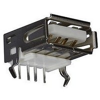
56-U04-E01
Description
USB CONNECTOR, RECEPTACLE, 4POS, THD
Manufacturer
Spectrum Control
Series
USB-Er
Datasheet
1.56-U04-E01.pdf
(258 pages)
Specifications of 56-U04-E01
Connector Type
USB
No. Of Contacts
4
Contact Termination
Right Angle Through Hole
Connector Mounting
PCB
Gender
Receptacle
Contact Plating
Gold
Product
USB Type A Connectors
Standard
USB
Number Of Ports
1
Features
Spectrum USB Filtered Connectors TYPE A R/A USB .05pF 5A 10VDC
Insulation Resistance
10 MOhms
Mounting Angle
Right
Number Of Positions / Contacts
4
Lead Free Status / RoHS Status
Contains lead / RoHS non-compliant
Lead Free Status / RoHS Status
Contains lead / RoHS non-compliant


145
Series 600 Hi-Density
Filtered Connectors
The miniaturization of electronic systems and sub-
systems is pushing designers to increase circuit
densities within smaller packages. To address this
growing need, Spectrum Control has developed a
line of filtered Hi-Density D-subminiature connectors.
This new line of connectors incorporates the high
performance and reliable filtering of Spectrum’s
standard D-subs in the Hi-Density format.
Features
s
s
s
s
s
Mechanical Specifications:
Same as Series 700 connectors, page 150.
Electrical Specifications: Hi-Density Connectors
Filter designation “G” for grounded contacts, “I” for insulated (not filtered) contacts.
Filter designation “O” for omitted contact and no hole in ground plane.
Ordering Information
Example:
D-Sub
Connector
Hi-Density
F - RoHS compliant version
SPECTRUM CONTROL INC. • 8031 Avonia Rd. • Fairview, PA 16415 • Phone: 814-474-2207 • Fax: 814-474-2208 • Web site: www.spectrumcontrol.com
SPECTRUM CONTROL GmbH • Hansastrasse 6 • 91126 Schwabach, Germany • Phone: (49)-9122-795-0 • Fax: (49)-9122-795-58
nations
Desig-
56 -
- Standard connector
Filter
Connectors designed to MIL-C-24308
Capacitance values from 85 pF to 4000 pF
Filter type feed-thru C
Selectively specify and filter each contact position
Available in feed-thru capacitive configurations
15
16
18
19
Circuits
Filter
C
56-605-015-LI
6 0 5 - 0 15
Shell
Size**
0 = 15
1 = 26
2 = 44
3 = 62
4 = 78
1000 pF
4000 pF
180 pF
Value
85 pF
Capacitance
Contact/Termination
1 - Pin to solder cup
2 - Pin to 90° PCB mount*
3 - Socket to PCB mount
4 - Socket to 90° PCB*
5 - Pin-socket adapter
7 - Pin to PCB mount
±25%
±25%
±25%
±25%
mount
Tol.
quency
Cut-off
(MHz)
3 dB
Max.
Fre-
5.1
1.3
60
28
Dielectric
-
standing
Voltage
With-
300V
300V
300V
300V
Special
0 = All
9 = Special
** Some shell sizes require minimum order quantity.
Note: VGA adapters also available. Consult factory
LI
Consult Spectrum Control for details.
positions
same
loading
Voltage DC
Working
-55°C to
+125°C
100V
100V
100V
100V
Insertion loss measured per MIL-STD-220, no load, 50 ohm source and load.
Electrical Specifications
Current Rating . . . . 3 Amps
RF Current Rating. . 0.3 Amps
Contact Resistance . . 15 milliohms maximum
UL Recognized. . . . . Under category of communication
This part number represents a Series 600 Hi-Density filtered D-Sub
connector with 15 contacts, pin-socket adapter configuration. The FT
filters have a capacitance value of 85 pF and the connector includes
4-40 locking inserts.
. . . . . . . . . . . . . . . .
MHz
—
—
—
5
8
Filter Designation
15 - 85 pF FT
16 - 180 pF FT
18 - 1,000 pF FT
19 - 4,000 pF FT
20 - Insulated contact
80
70
60
50
40
30
20
10
MHz
0
10
—
—
13
3
1MHz
Above curves represent application of proper
grounding fundamentals, for assistance consult
with Spectrum Control.
Typical Insertion Loss
Minimum Insertion Loss - Decibels (dB)
MHz
20
19
—
—
8
Capacitive Filter
10MHz
MHz
50
14
26
—
1
circuit accessories, File #E149046
MHz
100
20
31
1
8
* Required on right angle parts
Above data represents guaranteed minimum.
Frequency
MHz
100MHz
Options
50G = µ gold
GBL = Grounding board lock
200
10
25
37
6
LI = 4-40 inserts
S = Solder dip tails
18
16
19
15
MHz
500
16
18
32
45
GHz
1GHz 5GHz
21
25
35
48
1
GHz
22
26
41
52
2
GHz
20
24
39
47
5
Related parts for 56-U04-E01
Image
Part Number
Description
Manufacturer
Datasheet
Request
R

Part Number:
Description:
USB CONNECTOR, RECEPTACLE, 4POS, THD
Manufacturer:
Spectrum Control
Datasheet:
Part Number:
Description:
USB CONNECTOR, RECEPTACLE, 4POS, THD
Manufacturer:
Spectrum Control
Datasheet:
Part Number:
Description:
USB CONNECTOR, RECEPTACLE, 4POS, THD
Manufacturer:
Spectrum Control
Datasheet:

Part Number:
Description:
EMI/RFI Suppressors & Ferrites 15 POS CUSTOM MATE U
Manufacturer:
Spectrum Control

Part Number:
Description:
Power Line Filters Single Stage
Manufacturer:
Spectrum Control Inc.
Datasheet:
Part Number:
Description:
High Current Single Line Feed-thru Filters
Manufacturer:
Spectrum Control Inc.
Datasheet:
Part Number:
Description:
Switched And Fused Filtered Power Entry Modules
Manufacturer:
Spectrum Control Inc.
Datasheet:
Part Number:
Description:
Surface Mount Emi Filters
Manufacturer:
Spectrum Control Inc.
Datasheet:
Part Number:
Description:
(PSMx Series) Surface Mount EMI Filters
Manufacturer:
Spectrum Control
Datasheet: