56-U04-E01 Spectrum Control, 56-U04-E01 Datasheet - Page 213
56-U04-E01
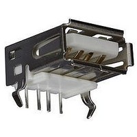
Manufacturer Part Number
56-U04-E01
Description
USB CONNECTOR, RECEPTACLE, 4POS, THD
Manufacturer
Spectrum Control
Series
USB-Er
Datasheet
1.56-U04-E01.pdf
(258 pages)
Specifications of 56-U04-E01
Connector Type
USB
No. Of Contacts
4
Contact Termination
Right Angle Through Hole
Connector Mounting
PCB
Gender
Receptacle
Contact Plating
Gold
Product
USB Type A Connectors
Standard
USB
Number Of Ports
1
Features
Spectrum USB Filtered Connectors TYPE A R/A USB .05pF 5A 10VDC
Insulation Resistance
10 MOhms
Mounting Angle
Right
Number Of Positions / Contacts
4
Lead Free Status / RoHS Status
Contains lead / RoHS non-compliant
Lead Free Status / RoHS Status
Contains lead / RoHS non-compliant


MIL-C-38999, Extended Shell
Ordering Information
Available connector styles and shell sizes for this MIL
series are shown on the following pages. Refer to these
pages and the information below to develop your
connector part number.
Custom Designs
Due to the versatility provided with this product design,
custom requirements can be readily accommodated.
Consult Spectrum Control for your specific needs.
Extended
Shell
Indicator
Contact Arrangements
Note: For availability of filtered connectors with custom requirements, such as mixed capacitance, insulated
SPECTRUM CONTROL INC. • 8031 Avonia Rd. • Fairview, PA 16415 • Phone: 814-474-2207 • Fax: 814-474-2208 • Web site: www.spectrumcontrol.com
SPECTRUM CONTROL GmbH • Hansastrasse 6 • 91126 Schwabach, Germany • Phone: (49)-9122-795-0 • Fax: (49)-9122-795-58
F
Note: First set of numbers represents Series II, second Series I,
3 #20
37 #22D
8-98
9-98
A98
14-35
15-35
D35
lines, ground lines or other contact arrangements, consult factory for specific part number.
third Series III & IV, and Fourth # of contacts and size.
MIL Indicator
8=MIL-C-38999
Shell Style
A - Wall mount (front panel)
B - Box mount (front panel)
C - Jam nut
D - Wall mount (rear panel)
E - Box mount (rear panel)
F - Hermetic jam nut
G - Hermetic wallmount
H - Straight plug
I - Hermetic box mount
8
41 #20
20-41
21-41
G41
10-98
11-98
7 #20
B98
Series Indicator
A=Series I
B=Series II
C=Series III
D=Series IV
C
55 #22D
16-35
17-35
E35
A
(First two digits shell size, second two contact arrangement)
10 #20
12-98
13-98
C98
Shell Size
9, 11, 13, 15, 17,
19, 21, 23 and 25
8, 10, 12, 14, 16,
18, 20, 22 and 24.
Series II only
Finish
B - Olive drab cadmium
D - Stainless steel, fused tin
N - Stainless steel,
E - Stainless steel, passivated
(hermetics only)
electrodeposited nickel
(hermetics only)
23
61 #20
24-61
25-61
J61
13 #22D
10-35
11-35
B35
B
66 #22D
14 #20 (A-N, R)
Materials and Finishes
Shell. . . . . . . . . . . . . . . . . As noted in Ordering Information
Backshell. . . . . . . . . . . . . . . . . . . Copper Alloy, Nickel Plate
Contacts . . . . . . . . . . . . . . . . . . Copper alloy, gold plate per
(For electrical specifications, see page 204.)
Contact
Arrangement
See below
18-35
19-35
F35
. . . . . . . . . . . . . . . . . . . . . . . . . . . . . . . . . . . .
35
1 #16 (P)
14-15
15-15
Contact/
Termination Type
P - Pin/PC tail
S - Pin/solder cup
B - Socket/PC tail
D - Socket/Solder cup
Alternate Shell Position
N, A, B, C, D - All
E - Series III only
D15
P
79 #22D
20-35
21-35
G35
18 #20
14-18
15-18
D18
N
100 #22D
22-35
23-35
H35
21 #16
22-21
23-21
Filter
Schematic
“1” = “C” feed-thru
“4” = Pi
Filter
Capacitance
Specify by using EIA
codes. Two significant
digits plus number of
zeros.
Example:
102 = 1000pF
303 = 30.0nF
104 =. 1µF
* See table page 204
H21
4
MIL-G-45204
128 #22D
24-35
25-35
J35
22 #22D
12-35
13-35
C35
102
213
Related parts for 56-U04-E01
Image
Part Number
Description
Manufacturer
Datasheet
Request
R

Part Number:
Description:
USB CONNECTOR, RECEPTACLE, 4POS, THD
Manufacturer:
Spectrum Control
Datasheet:
Part Number:
Description:
USB CONNECTOR, RECEPTACLE, 4POS, THD
Manufacturer:
Spectrum Control
Datasheet:
Part Number:
Description:
USB CONNECTOR, RECEPTACLE, 4POS, THD
Manufacturer:
Spectrum Control
Datasheet:

Part Number:
Description:
EMI/RFI Suppressors & Ferrites 15 POS CUSTOM MATE U
Manufacturer:
Spectrum Control

Part Number:
Description:
Power Line Filters Single Stage
Manufacturer:
Spectrum Control Inc.
Datasheet:
Part Number:
Description:
High Current Single Line Feed-thru Filters
Manufacturer:
Spectrum Control Inc.
Datasheet:
Part Number:
Description:
Switched And Fused Filtered Power Entry Modules
Manufacturer:
Spectrum Control Inc.
Datasheet:
Part Number:
Description:
Surface Mount Emi Filters
Manufacturer:
Spectrum Control Inc.
Datasheet:
Part Number:
Description:
(PSMx Series) Surface Mount EMI Filters
Manufacturer:
Spectrum Control
Datasheet: