56-U04-E01 Spectrum Control, 56-U04-E01 Datasheet - Page 171
56-U04-E01
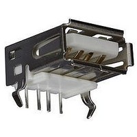
Manufacturer Part Number
56-U04-E01
Description
USB CONNECTOR, RECEPTACLE, 4POS, THD
Manufacturer
Spectrum Control
Series
USB-Er
Datasheet
1.56-U04-E01.pdf
(258 pages)
Specifications of 56-U04-E01
Connector Type
USB
No. Of Contacts
4
Contact Termination
Right Angle Through Hole
Connector Mounting
PCB
Gender
Receptacle
Contact Plating
Gold
Product
USB Type A Connectors
Standard
USB
Number Of Ports
1
Features
Spectrum USB Filtered Connectors TYPE A R/A USB .05pF 5A 10VDC
Insulation Resistance
10 MOhms
Mounting Angle
Right
Number Of Positions / Contacts
4
Lead Free Status / RoHS Status
Contains lead / RoHS non-compliant
Lead Free Status / RoHS Status
Contains lead / RoHS non-compliant


171
F - RoHS compliant version
D-Subminiature
Part Numbering System
Ordering Information
Example:
Filtered
D-Subminiature
Connectors
SPECTRUM CONTROL INC. • 8031 Avonia Rd. • Fairview, PA 16415 • Phone: 814-474-2207 • Fax: 814-474-2208 • Web site: www.spectrumcontrol.com
SPECTRUM CONTROL GmbH • Hansastrasse 6 • 91126 Schwabach, Germany • Phone: (49)-9122-795-0 • Fax: (49)-9122-795-58
To assist your efforts in selecting the correct Filtered Connector to meet your needs,
we have developed a part numbering system. All of the standard products are shown
in their respective catalog pages.
in a socket to straight PCB mount configuration. All connector positions have
a capacitance value of 840 pF and there are 4-40 threads on mounting flange.
- Standard connector
56 -
Part number 56-513-012-TI represents a Series 500 connector with 15 contacts
Product
Series
1 = Series 100
4 = Series F
5 = Series 500
6 = Series 600
7 = Series 700
C.O.B.
Ferrite
Low Profile
Hi-Density
High
Performance
56-513-012-TI
5 1 3 - 0 12
Contact Type/Termination
1 = Pin to solder cup
2 = Pin to 90° PCB mount
3 = Socket to straight PCB mount
4 = Socket to 90° PCB mount
5 = Pin-socket adapter
6 = Socket to solder cup
7 = Pin to straight PCB mount
Styles available for:
Series 400 only 2, 3, 4, 7
Series 100 1 thru 7
Series 500 only 2, 3, 4 & 7
Series 600 only 1, 2, 3, 4, 5
Series 700 1 thru 6
Note: 1 can be Pin to solder cup
or Pin to PCB for Series 700.
See charts pages 151-170.
Shell Size
Series 400,
Series 100 & 500
Series 600
Hi-Density
Series 700
0 = 9 Contacts
1 = 15 Contacts
2 = 25 Contacts
3 = 37 Contacts
0 = 15 Contacts
1 = 26 Contacts
2 = 44 Contacts
3 = 62 Contacts
4 = 78 Contacts
0 = 9 Contacts
1 = 15 Contacts
2 = 25 Contacts
3 = 37 Contacts
4 = 50 Contacts
-
TI
Line
Filtering
0 = All
9 = Special
positions
same
loading
(Series
600 only)
Capacitance
Value
Series 400
Series 100
Series 500
Series 600
Series 700
01 = Always
02 = 100 pF
03 = 220 pF
04 = 470 pF
05 = 820 pF
06 = 1500 pF
07 = 5600 pF
08 = 50 pF
09 = 180 pF
10 = 1000 pF
11 = 2200 pF
12 = 47 nF
10 = 120 pF
11 = 440 pF
12 = 840 pF
13 = 1000 pF
14 = 1500 pF
15 = 85 pF FT
16 = 180 pF FT
18 = 1000 pF FT
19 = 4000 pF FT
20 = Insulated
See filter specifi-
cation chart on
page 149 and
select part numbers
from Series 700
charts pages
151-170.
contact
Options
See options descriptions
on page 172
add suffix ending
Series 100
Series F
Series 500
Series 600 Hi-Density
Series 700
For option combinations, consult factory.
GBLF = Grounded board lock
GBL6 = for .062" boards (straight
GBL9 = for .093" boards (straight
GBL6 - for .062" boards (1.57mm)
GBL = Grounded board lock
GBL = Ground board lock
GBL = Grounded board lock
50G = 50 µ (1.27 µm) gold
50G = 50 µ (1.27 µm) gold plating
LIM = Metric M3.0 self-locking threads
MIB - M3 thread on rear of flange
TIB - 4-40 thread on rear of flange
GB = Metal bracket provides ground
3G - 30µ" gold (.76um)
5G - 50µ" gold (1.27um)
TIF - 4-40 thread on front of flange
GB - no board locks
HD =Hi-Density
GL - includes grounding board lock
GF - GL and jack screws
JS = Jackscrew mounting
JS - Jack screws
TI = 4-40 threads on mounting
LI = 4-40 UNC inserts
LI = 4-40 UNC inserts
M - M3 thread
S = Solder dipped tails
S = Solder dipped tails
_ - .120 thru-hole and 15µ" gold (.38um)
T - 4-40 threads
_ - No GBL attached
J - jack screws
SC and Straight PCBs
Right Angles and Adapters
and 4-40 threads
(15 socket only)
flange (.125" hole if not
selected)
includes 4-40 threads
(available only on 90° PCB)
and ferrite slab
provides enhanced LC
performance. (Available
only on 90° PCB)
connection, includes 4-40
self-locking threads (for right angle
mount only)
(right angle)
PCB mount) (1.57mm)
PCB mount (2.36mm)
Related parts for 56-U04-E01
Image
Part Number
Description
Manufacturer
Datasheet
Request
R

Part Number:
Description:
USB CONNECTOR, RECEPTACLE, 4POS, THD
Manufacturer:
Spectrum Control
Datasheet:
Part Number:
Description:
USB CONNECTOR, RECEPTACLE, 4POS, THD
Manufacturer:
Spectrum Control
Datasheet:
Part Number:
Description:
USB CONNECTOR, RECEPTACLE, 4POS, THD
Manufacturer:
Spectrum Control
Datasheet:

Part Number:
Description:
EMI/RFI Suppressors & Ferrites 15 POS CUSTOM MATE U
Manufacturer:
Spectrum Control

Part Number:
Description:
Power Line Filters Single Stage
Manufacturer:
Spectrum Control Inc.
Datasheet:
Part Number:
Description:
High Current Single Line Feed-thru Filters
Manufacturer:
Spectrum Control Inc.
Datasheet:
Part Number:
Description:
Switched And Fused Filtered Power Entry Modules
Manufacturer:
Spectrum Control Inc.
Datasheet:
Part Number:
Description:
Surface Mount Emi Filters
Manufacturer:
Spectrum Control Inc.
Datasheet:
Part Number:
Description:
(PSMx Series) Surface Mount EMI Filters
Manufacturer:
Spectrum Control
Datasheet: