56-U04-E01 Spectrum Control, 56-U04-E01 Datasheet - Page 44
56-U04-E01
Manufacturer Part Number
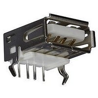
56-U04-E01
Description
USB CONNECTOR, RECEPTACLE, 4POS, THD
Manufacturer
Spectrum Control
Series
USB-Er
Datasheet
1.56-U04-E01.pdf
(258 pages)
Specifications of 56-U04-E01
Connector Type
USB
No. Of Contacts
4
Contact Termination
Right Angle Through Hole
Connector Mounting
PCB
Gender
Receptacle
Contact Plating
Gold
Product
USB Type A Connectors
Standard
USB
Number Of Ports
1
Features
Spectrum USB Filtered Connectors TYPE A R/A USB .05pF 5A 10VDC
Insulation Resistance
10 MOhms
Mounting Angle
Right
Number Of Positions / Contacts
4
Lead Free Status / RoHS Status
Contains lead / RoHS non-compliant
Lead Free Status / RoHS Status
Contains lead / RoHS non-compliant


44
Terminology
Inductance
Inductance is the ability of a conductor to produce
induced voltage when the current varies. The symbol
for inductance is L and the unit is Henry (H).
Inductance of Spectrum Control’s inductors is measured
by using an HP4191A/HP4291A/HP4286A Impedance
Analyzer.
Impedance
Impedance is the measure of opposition to a current.
The symbol for impedance is Z and the unit is Ohm.
Where R is the resistance (not DC resistance) and X
the reactance. Z , R and X
Impedance of Spectrum Control’s chip beads is measured
by using an HP4291A/HP4286A Impedance Analyzer.
Direct Current Resistance (DCR)
DCR is the resistance of the component measured
with direct current. DCR of Spectrum Control’s inductive
components is measured by using an HP4338A
milli-ohmmeter.
Maximum Rated Current
Maximum rated current is a measure of the current
carrying capacity of the component. When the maximum
rated current is applied to the component, the temperature
rise shall not exceed 20°C.
Equivalent Circuit of an Inductor
Using an ideal resistor, an ideal capacitor and an ideal
inductor, a real inductor can be simulated. The resistor
component in an equivalent circuit comes from the DC
resistance of the electrode and the electromagnetic
loss. The capacitive component comes from the parasitic
capacitance of the coil.
SPECTRUM CONTROL INC. • 8031 Avonia Rd. • Fairview, PA 16415 • Phone: 814-474-2207 • Fax: 814-474-2208 • Web site: www.spectrumcontrol.com
SPECTRUM CONTROL GmbH • Hansastrasse 6 • 91126 Schwabach, Germany • Phone: (49)-9122-795-0 • Fax: (49)-9122-795-58
1 H = 1,000 mH (milli Henry)
1 H = 1,000,000 µH (micro Henry)
1 H = 1,000,000,000 nH (nano Henry)
R
Z =
√
L
R
are all frequency dependent.
2
+ X
C
L
L
2
L
is
Self-Resonant Frequency (SRF)
When the frequency changes, the capacitive reactance
X
resonance frequency is the frequency at which the X
equals X
shows maximum impedance and a minimum line current.
The SRF shall generally be specified as at least twice
the application frequency, except for some special
applications. The SRF of Spectrum Control’s inductors
is measured by using an HP4291A Impedance
Analyzer/HP8753D Network Analyzer.
Quality Factor (Q)
Q is the quality factor of an inductor. It is the ratio of the
inductor’s ability to produce self-induced voltage over
the resistance that reduces the current and the induced
voltage. It can be considered as the ratio of the inductor’s
capability to store energy over the capability to consume
energy.
Q is highly dependent on frequency. Q values of Spectrum
Control’s inductors are measured by using an HP4291A
Impedance Analyzer/HP8753D Network Analyzer.
c
and inductive reactance X
c
. At self-resonance frequency, the inductor
Q = X
R
L
L
also change. The self-
L
Related parts for 56-U04-E01
Image
Part Number
Description
Manufacturer
Datasheet
Request
R

Part Number:
Description:
USB CONNECTOR, RECEPTACLE, 4POS, THD
Manufacturer:
Spectrum Control
Datasheet:
Part Number:
Description:
USB CONNECTOR, RECEPTACLE, 4POS, THD
Manufacturer:
Spectrum Control
Datasheet:
Part Number:
Description:
USB CONNECTOR, RECEPTACLE, 4POS, THD
Manufacturer:
Spectrum Control
Datasheet:

Part Number:
Description:
EMI/RFI Suppressors & Ferrites 15 POS CUSTOM MATE U
Manufacturer:
Spectrum Control

Part Number:
Description:
Power Line Filters Single Stage
Manufacturer:
Spectrum Control Inc.
Datasheet:
Part Number:
Description:
High Current Single Line Feed-thru Filters
Manufacturer:
Spectrum Control Inc.
Datasheet:
Part Number:
Description:
Switched And Fused Filtered Power Entry Modules
Manufacturer:
Spectrum Control Inc.
Datasheet:
Part Number:
Description:
Surface Mount Emi Filters
Manufacturer:
Spectrum Control Inc.
Datasheet:
Part Number:
Description:
(PSMx Series) Surface Mount EMI Filters
Manufacturer:
Spectrum Control
Datasheet: