56-U04-E01 Spectrum Control, 56-U04-E01 Datasheet - Page 62
56-U04-E01
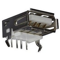
Manufacturer Part Number
56-U04-E01
Description
USB CONNECTOR, RECEPTACLE, 4POS, THD
Manufacturer
Spectrum Control
Series
USB-Er
Datasheet
1.56-U04-E01.pdf
(258 pages)
Specifications of 56-U04-E01
Connector Type
USB
No. Of Contacts
4
Contact Termination
Right Angle Through Hole
Connector Mounting
PCB
Gender
Receptacle
Contact Plating
Gold
Product
USB Type A Connectors
Standard
USB
Number Of Ports
1
Features
Spectrum USB Filtered Connectors TYPE A R/A USB .05pF 5A 10VDC
Insulation Resistance
10 MOhms
Mounting Angle
Right
Number Of Positions / Contacts
4
Lead Free Status / RoHS Status
Contains lead / RoHS non-compliant
Lead Free Status / RoHS Status
Contains lead / RoHS non-compliant


62
Thru-hole Filters
High Frequency PCB Filters
The economical High Frequency PCB Filter offers
electrical characteristics which allow many devices
to meet most government and industry specifications
for EMI control, while providing good electrostatic
discharge protection.
terminated within the filter’s thermoset epoxy body.
three ways. First is the low cost of the filter assembly.
Second is the economy of installation. Three silver
plated leads are inserted into holes in a printed circuit
board which has a ground path circuit, for conventional
flows-soldering with other components. No special
mounting plate or brackets are needed and when the
holes are placed as recommended in a .062 (1.57mm)
thick board, no lead trimming is required. Elimination
of hand soldering provides opportunities for improved
quality in addition to applied-cost benefits.
source of an EMI problem, potentially eliminating the
need for additional filtering at other points in the circuit.
Features
s
s
s
s
s
Circuit Schematic
SPECTRUM CONTROL INC. • 8031 Avonia Rd. • Fairview, PA 16415 • Phone: 814-474-2207 • Fax: 814-474-2208 • Web site: www.spectrumcontrol.com
SPECTRUM CONTROL GmbH • Hansastrasse 6 • 91126 Schwabach, Germany • Phone: (49)-9122-795-0 • Fax: (49)-9122-795-58
Recommended PCB Hole Layout
Provides EMI filtering to protect low power digital
circuits - helps equipment meet FCC and VDE
specifications
Mounts directly to printed circuit board with no bracket
or plate for lower applied costs - can be flow soldered
with other components
Encapsulated for environmental protection
Mounts on PCB to begin filtering at the source
of the problem
Built-in standoffs permit cleaning or coating under
the filter
A lossy ferrite filter with a center ground lead is
The High Frequency PCB Filter offers savings
A third savings results from placing a filter at the
+
.055
(1.4
Dia.
(7.62
.300
±0.05
±.002
Input
±0.13
±.005
)
(15.24
.600
)
+
(1.02
.040
±.010
±0.25
Dia.
±0.05
)
±.002
)
Ground
Dimensions in inches (mm)
Pi
+
(1.4
.055
Dia.
±0.005
±.002
)
Output
Typical Electrical Characteristics
Current . . . . . . . . . . . . . . . Max. 10A DC; 0.3A RF
Operating Voltage . . . . . . . . Max. 50 VDC, -25°C +85°C
Capacitance . . . . . . . . . . . . 800 pF min.
Dissipation Factor . . . . . . . . 0.1 Max.
Dielectric
Withstanding Voltage . . . . . 125 VDC for 5 seconds
Insulation Resistance. . . . . . Min. 100 MegOhms at 100 VDC
Direct Current
Resistance. . . . . . . . . . . . . . 0.002 ohms Max.
Minimum No-Load
Insertion Loss . . . . . . . . . . . Per MIL-STD-220 at 25°C; PCB
Preformed to Recommended Mounting Configuration
Part Number 842448-2
. . . . . . . . . . . . . . . . . . . . .
Recommended Mounting Configuration
Standard Configuration
(1.57)
.062
Ref.
(0.81)
.032
Dia.
1.040 (26.42)
(7.62
.300
±.010
±0.25
(7.62
.300
)
Ground
Lead
(13.21)
±0.38
±.015
.520
Ref.
(15.24
.600
)
for 2 minutes and 25°C
10dB @ 25 MHz
15dB @ 50 MHZ
20dB @ 100 MHz-1GHz
mounted, 50 ohm strip line
±.030
±0.76
3dB @ 8 MHz
Ground
)
Lead
Part Number 842448-1
Dimensions in inches (mm)
Dimensions in inches (mm)
(1.02)
.040
Dia.
(6.10
.240
±0.51
±.020
)
(0.38)
.015
.062 (1.57) Ref.
Ref.
(3.18
.125
(5.08
.200
±.025
±0.64
±.010
±0.25
)
)
Related parts for 56-U04-E01
Image
Part Number
Description
Manufacturer
Datasheet
Request
R

Part Number:
Description:
USB CONNECTOR, RECEPTACLE, 4POS, THD
Manufacturer:
Spectrum Control
Datasheet:
Part Number:
Description:
USB CONNECTOR, RECEPTACLE, 4POS, THD
Manufacturer:
Spectrum Control
Datasheet:
Part Number:
Description:
USB CONNECTOR, RECEPTACLE, 4POS, THD
Manufacturer:
Spectrum Control
Datasheet:

Part Number:
Description:
EMI/RFI Suppressors & Ferrites 15 POS CUSTOM MATE U
Manufacturer:
Spectrum Control

Part Number:
Description:
Power Line Filters Single Stage
Manufacturer:
Spectrum Control Inc.
Datasheet:
Part Number:
Description:
High Current Single Line Feed-thru Filters
Manufacturer:
Spectrum Control Inc.
Datasheet:
Part Number:
Description:
Switched And Fused Filtered Power Entry Modules
Manufacturer:
Spectrum Control Inc.
Datasheet:
Part Number:
Description:
Surface Mount Emi Filters
Manufacturer:
Spectrum Control Inc.
Datasheet:
Part Number:
Description:
(PSMx Series) Surface Mount EMI Filters
Manufacturer:
Spectrum Control
Datasheet: