56-U04-E01 Spectrum Control, 56-U04-E01 Datasheet - Page 148
56-U04-E01
Manufacturer Part Number
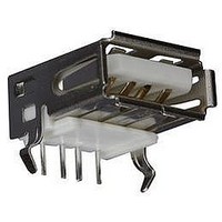
56-U04-E01
Description
USB CONNECTOR, RECEPTACLE, 4POS, THD
Manufacturer
Spectrum Control
Series
USB-Er
Datasheet
1.56-U04-E01.pdf
(258 pages)
Specifications of 56-U04-E01
Connector Type
USB
No. Of Contacts
4
Contact Termination
Right Angle Through Hole
Connector Mounting
PCB
Gender
Receptacle
Contact Plating
Gold
Product
USB Type A Connectors
Standard
USB
Number Of Ports
1
Features
Spectrum USB Filtered Connectors TYPE A R/A USB .05pF 5A 10VDC
Insulation Resistance
10 MOhms
Mounting Angle
Right
Number Of Positions / Contacts
4
Lead Free Status / RoHS Status
Contains lead / RoHS non-compliant
Lead Free Status / RoHS Status
Contains lead / RoHS non-compliant


Hi-Density Filtered Adapter
for Telecommunications
Filter Performance
Insertion loss measured per MIL-STD-220, no load, 50 ohm source
and load. Above data represents guaranteed minimum.
Part Number for Ordering: #56-645-002
SPECTRUM CONTROL INC. • 8031 Avonia Rd. • Fairview, PA 16415 • Phone: 814-474-2207 • Fax: 814-474-2208 • Web site: www.spectrumcontrol.com
SPECTRUM CONTROL GmbH • Hansastrasse 6 • 91126 Schwabach, Germany • Phone: (49)-9122-795-0 • Fax: (49)-9122-795-58
(2.08)
.082
#4-40 UNC - 2B
Locking Inserts
4 plcs.
(11.18)
.440
(1.04)
.041
41
100 MHz . . . . . . . . . . . . . . . . . . . . . 20 dB
500 MHz . . . . . . . . . . . . . . . . . . . . . 32 dB
20 MHz . . . . . . . . . . . . . . . . . . . . . . 7 dB
50 MHz . . . . . . . . . . . . . . . . . . . . . 14 dB
1 GHz . . . . . . . . . . . . . . . . . . . . . 35 dB
2 GHz . . . . . . . . . . . . . . . . . . . . . 41 dB
5 GHz . . . . . . . . . . . . . . . . . . . . . 39 dB
Position numbers
shown for reference
(6.17)
.243
(4.83)
.190
Minimum Insertion Loss
.0475 (1.21)
21
(1.27)
.050
.095 (2.41)
60
2
2.635 (66.93)
2.062 (52.37)
Side View
Socket Face
2.406 (61.11)
Pin Face
(25.40)
(13.21)
1.000
(52.81)
.520
2.079
38
77
(6.05)
(4.83)
.238
.190
Dimensions in inches (mm)
19
58
(10.57)
.416
(15.62)
.615
100
50
50
40
30
20
10
0
0
0
1MHz
Above curves represent application of proper
grounding fundamentals, for assistance consult
with Spectrum Control.
* Reference Bellcore TR-NWT-1089, V pp = 1000V
Typical Insertion Loss
Pulse Wave Form* (10 x 1000)
t p
Peak Value – V pp
t r
1
Hall Value –
10MHz
2
t - - Time - - msec
Frequency
Vpp
100MHz
2
10 x 1000 Waveform
3
e t
4
Test Waveform
Parameters
t r = 10μsec
t p = 1000μs
1GHz
5
5GHz
6
148
Related parts for 56-U04-E01
Image
Part Number
Description
Manufacturer
Datasheet
Request
R

Part Number:
Description:
USB CONNECTOR, RECEPTACLE, 4POS, THD
Manufacturer:
Spectrum Control
Datasheet:
Part Number:
Description:
USB CONNECTOR, RECEPTACLE, 4POS, THD
Manufacturer:
Spectrum Control
Datasheet:
Part Number:
Description:
USB CONNECTOR, RECEPTACLE, 4POS, THD
Manufacturer:
Spectrum Control
Datasheet:

Part Number:
Description:
EMI/RFI Suppressors & Ferrites 15 POS CUSTOM MATE U
Manufacturer:
Spectrum Control

Part Number:
Description:
Power Line Filters Single Stage
Manufacturer:
Spectrum Control Inc.
Datasheet:
Part Number:
Description:
High Current Single Line Feed-thru Filters
Manufacturer:
Spectrum Control Inc.
Datasheet:
Part Number:
Description:
Switched And Fused Filtered Power Entry Modules
Manufacturer:
Spectrum Control Inc.
Datasheet:
Part Number:
Description:
Surface Mount Emi Filters
Manufacturer:
Spectrum Control Inc.
Datasheet:
Part Number:
Description:
(PSMx Series) Surface Mount EMI Filters
Manufacturer:
Spectrum Control
Datasheet: