56-U04-E01 Spectrum Control, 56-U04-E01 Datasheet - Page 40
56-U04-E01
Manufacturer Part Number
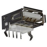
56-U04-E01
Description
USB CONNECTOR, RECEPTACLE, 4POS, THD
Manufacturer
Spectrum Control
Series
USB-Er
Datasheet
1.56-U04-E01.pdf
(258 pages)
Specifications of 56-U04-E01
Connector Type
USB
No. Of Contacts
4
Contact Termination
Right Angle Through Hole
Connector Mounting
PCB
Gender
Receptacle
Contact Plating
Gold
Product
USB Type A Connectors
Standard
USB
Number Of Ports
1
Features
Spectrum USB Filtered Connectors TYPE A R/A USB .05pF 5A 10VDC
Insulation Resistance
10 MOhms
Mounting Angle
Right
Number Of Positions / Contacts
4
Lead Free Status / RoHS Status
Contains lead / RoHS non-compliant
Lead Free Status / RoHS Status
Contains lead / RoHS non-compliant


40
Surface Mount High Frequency
Ceramic Chip Inductors
Features
s
s
s
s
s
s
s
s
Applications
s
s
s
s
s
Part Numbering System
Example:
Land Patterns and Soldering
Temperature Profiles
s
SPECTRUM CONTROL INC. • 8031 Avonia Rd. • Fairview, PA 16415 • Phone: 814-474-2207 • Fax: 814-474-2208 • Web site: www.spectrumcontrol.com
SPECTRUM CONTROL GmbH • Hansastrasse 6 • 91126 Schwabach, Germany • Phone: (49)-9122-795-0 • Fax: (49)-9122-795-58
CIN
Series
Ceramic
INductor
High Q characteristics at high frequency and
self-resonant frequency
Available in standard EIA/EIAJ chip sizes
(0402/1005, 0603/1608, 0805/2012, etc.)
Excellent solderability is achieved from a nickel barrier
with a solder overplate
Parts are suitable for flow or re-flow soldering
Available in tape and reel for easy placement
Provides high reliability in a temperature range
of -40°C to +125°C over a wide range of humidity
Parts can be used at frequency up to 6 GHz with
Q values of 10 to 23 at 100 MHz, up to 63 at 800 MHz
Standard inductance range of 1.0 to 100 nH
Designed to address surface mountable inductor
needs at high frequency
Telecommunications equipment (cellular phones,
pagers, etc.)
Computer communication equipment
Radar detectors
Any high frequency circuits
See page 45.
CIN-0402-H8D2JB
-
Part Size
EIA Size
(Length x Width)
0402
-
Material
Characteristic
Determined
by the desired
electrical
characteristic
H
Inductance Code
Value is measured in nH
D stands for decimal point
8D2 = 8.2 nH
Note: The ceramic chip inductors have a blue strip on one side of the
Packaging Specifications
and Storage Requirements
s
8D2
See page 46.
part to allow for proper placement.
The blue strip needs to be on the top side, away from the board
to get proper electrical characteristics.
L
Tolerance Code
S = ±0.3 nH
T = ±3%
J = ±5%
K = ±10%
M = ±20%
Note: Please check tables for available
B
tolerances on individual parts.
J
W
Packaging
7 = 7 inch reel
3 = 13 inch reel
B
H
Related parts for 56-U04-E01
Image
Part Number
Description
Manufacturer
Datasheet
Request
R

Part Number:
Description:
USB CONNECTOR, RECEPTACLE, 4POS, THD
Manufacturer:
Spectrum Control
Datasheet:
Part Number:
Description:
USB CONNECTOR, RECEPTACLE, 4POS, THD
Manufacturer:
Spectrum Control
Datasheet:
Part Number:
Description:
USB CONNECTOR, RECEPTACLE, 4POS, THD
Manufacturer:
Spectrum Control
Datasheet:

Part Number:
Description:
EMI/RFI Suppressors & Ferrites 15 POS CUSTOM MATE U
Manufacturer:
Spectrum Control

Part Number:
Description:
Power Line Filters Single Stage
Manufacturer:
Spectrum Control Inc.
Datasheet:
Part Number:
Description:
High Current Single Line Feed-thru Filters
Manufacturer:
Spectrum Control Inc.
Datasheet:
Part Number:
Description:
Switched And Fused Filtered Power Entry Modules
Manufacturer:
Spectrum Control Inc.
Datasheet:
Part Number:
Description:
Surface Mount Emi Filters
Manufacturer:
Spectrum Control Inc.
Datasheet:
Part Number:
Description:
(PSMx Series) Surface Mount EMI Filters
Manufacturer:
Spectrum Control
Datasheet: