56-U04-E01 Spectrum Control, 56-U04-E01 Datasheet - Page 181
56-U04-E01
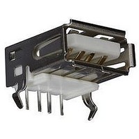
Manufacturer Part Number
56-U04-E01
Description
USB CONNECTOR, RECEPTACLE, 4POS, THD
Manufacturer
Spectrum Control
Series
USB-Er
Datasheet
1.56-U04-E01.pdf
(258 pages)
Specifications of 56-U04-E01
Connector Type
USB
No. Of Contacts
4
Contact Termination
Right Angle Through Hole
Connector Mounting
PCB
Gender
Receptacle
Contact Plating
Gold
Product
USB Type A Connectors
Standard
USB
Number Of Ports
1
Features
Spectrum USB Filtered Connectors TYPE A R/A USB .05pF 5A 10VDC
Insulation Resistance
10 MOhms
Mounting Angle
Right
Number Of Positions / Contacts
4
Lead Free Status / RoHS Status
Contains lead / RoHS non-compliant
Lead Free Status / RoHS Status
Contains lead / RoHS non-compliant


181
Series E (ESD/EFT)
Transient Protected Connectors
These fully integrated connectors and adapters provide
protection from Electro Static Discharge (ESD) and
Electronically Fast Transients (EFT) that can damage
or even destroy your equipment. The connectors are
designed to meet various IEC 61000-4-21, EN 61000-4-2
and IEC 61000-4 standards, and are offered in a wide
range of clamping voltages to fit your specific application.
The connectors have integrated ESD transient voltage
suppressors from Littelfuse
standard sizes and are “drop in” replacements for
unprotected connectors.
condition your signals to handle EMI issues at the same
time or with as little as a 0.05 pF to protect the integrity of
your signal in high speed or digital applications.
Features
s
s
s
s
s
s
s
SPECTRUM CONTROL INC. • 8031 Avonia Rd. • Fairview, PA 16415 • Phone: 814-474-2207 • Fax: 814-474-2208 • Web site: www.spectrumcontrol.com
SPECTRUM CONTROL GmbH • Hansastrasse 6 • 91126 Schwabach, Germany • Phone: (49)-9122-795-0 • Fax: (49)-9122-795-58
ESD/EFT protection at the I/O ports – Prevents the
transients from entering the system before they can
cause harm or create EMI problems.
Low ground impedance – The metallic shell provides
minimal impedance to direct the damaging transient
spikes to ground, which is essential for proper protection.
Removal of ground traces from the board –
This eliminates potential line-to-line noise problems
and spark-overs between ground and signal lines.
Complete protection – All lines, including ground
lines, have bi-directional protection.
Efficient space utilization – Standard footprints save
valuable board space in terms of not only components,
but also extra ground traces.
Fewer components – Reduces total number of
components purchased, stocked, placed and tested;
yielding the savings of all the hidden costs involved
in these activities, while reducing your supplier base.
Available capacitance – Available with various
capacitance values to supply low pass properties
along with the transient protection, thus supplying
ESD/EFT and EMI protection all in one complete
package. The metal shell also provides EMI shielding
of system. Parts are available with capacitance
values less than 50 pF for digital and very high
speed signal lines.
They are available with various capacitance levels to
®
, are available in industry
Mechanical Specifications
Front Shell . . . . . . . . . . . Steel, tin plated
Housing. . . . . . . . . . . . . 94V-0 rated thermoplastic, black
Eyelets . . . . . . . . . . . . . . Brass, tin plated
Threaded Inserts . . . . . . . Zinc
Boardlocks . . . . . . . . . . . Copper alloy, tin-lead plated
Pin Contacts . . . . . . . . . Brass
Socket Contacts . . . . . . . Phosphor Bronze
Contact Plating . . . . . . . Duplex plated as follows: 15uin (.38um)
Current Rating. . . . . . . . 5 Amp per pin
Operating Temp . . . . . . . -55°C to +125°C
. . . . . . . . . . . . . . . . . . .
. . . . . . . . . . . . . . . . . . .
. . . . . . . . . . . . . . . . . . .
Typical Time-Voltage Curve of Transient Spike on Integrated
Protected Connector with Capacitance (Parts with Working
Voltage Code starting with 0)
Typical Time-Voltage Curve of Low Capacitance Integrated
Protection (Parts with Working Voltage Code starting with P)
Typical Time-Voltage Curves
Peak Current
ESD Event
Clamped Waveform
Protection Trigger
Overshoot Voltage
Potential Voltage
gold on mating end, with entire contact
50uin (1.27um) min. nickel underplated
and flash gold finish.
Voltage Across
Connector
ESD Transient Spike
Waveform
Time
Time
Current Through
Connector
Clamp Voltage
System Voltage Limit
Clamping Voltage
Related parts for 56-U04-E01
Image
Part Number
Description
Manufacturer
Datasheet
Request
R

Part Number:
Description:
USB CONNECTOR, RECEPTACLE, 4POS, THD
Manufacturer:
Spectrum Control
Datasheet:
Part Number:
Description:
USB CONNECTOR, RECEPTACLE, 4POS, THD
Manufacturer:
Spectrum Control
Datasheet:
Part Number:
Description:
USB CONNECTOR, RECEPTACLE, 4POS, THD
Manufacturer:
Spectrum Control
Datasheet:

Part Number:
Description:
EMI/RFI Suppressors & Ferrites 15 POS CUSTOM MATE U
Manufacturer:
Spectrum Control

Part Number:
Description:
Power Line Filters Single Stage
Manufacturer:
Spectrum Control Inc.
Datasheet:
Part Number:
Description:
High Current Single Line Feed-thru Filters
Manufacturer:
Spectrum Control Inc.
Datasheet:
Part Number:
Description:
Switched And Fused Filtered Power Entry Modules
Manufacturer:
Spectrum Control Inc.
Datasheet:
Part Number:
Description:
Surface Mount Emi Filters
Manufacturer:
Spectrum Control Inc.
Datasheet:
Part Number:
Description:
(PSMx Series) Surface Mount EMI Filters
Manufacturer:
Spectrum Control
Datasheet: