56-U04-E01 Spectrum Control, 56-U04-E01 Datasheet - Page 17
56-U04-E01
Manufacturer Part Number
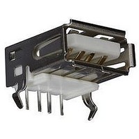
56-U04-E01
Description
USB CONNECTOR, RECEPTACLE, 4POS, THD
Manufacturer
Spectrum Control
Series
USB-Er
Datasheet
1.56-U04-E01.pdf
(258 pages)
Specifications of 56-U04-E01
Connector Type
USB
No. Of Contacts
4
Contact Termination
Right Angle Through Hole
Connector Mounting
PCB
Gender
Receptacle
Contact Plating
Gold
Product
USB Type A Connectors
Standard
USB
Number Of Ports
1
Features
Spectrum USB Filtered Connectors TYPE A R/A USB .05pF 5A 10VDC
Insulation Resistance
10 MOhms
Mounting Angle
Right
Number Of Positions / Contacts
4
Lead Free Status / RoHS Status
Contains lead / RoHS non-compliant
Lead Free Status / RoHS Status
Contains lead / RoHS non-compliant


EMI/RFI Filter and Capacitor
Performance Testing
The resin sealed and hermetically sealed filters shown in
this section have been designed to meet the requirements
of this test plan as applicable. Group I tests are typically
performed on most product. Groups II, III and IV tests are
performed per specification requirements.
* Acceptance tests typically performed on most products.
†
SPECTRUM CONTROL INC. • 8031 Avonia Rd. • Fairview, PA 16415 • Phone: 814-474-2207 • Fax: 814-474-2208 • Web site: www.spectrumcontrol.com
SPECTRUM CONTROL GmbH • Hansastrasse 6 • 91126 Schwabach, Germany • Phone: (49)-9122-795-0 • Fax: (49)-9122-795-58
Group
Methods are from MIL-STD-202
Test
IV
III
II
I
Order
Test
*1
*2
*3
*4
*5
*6
*7
*8
*9
of
1
2
3
4
5
6
1
2
3
4
1
2
Visual and Mechanical Examination
Materials, Designs, Construction
and Workmanship
Physical Dimensions and Marking
Seal
Capacitance
Dielectric Withstanding Voltage
Insulation Resistance
Voltage Drop
Insertion Loss
Temperature Rise
Overload
Barometric Pressure
Shock
Vibration
Moisture Resistance
Terminal Strength
Resistance to Soldering Heat
Thermal Shock
Immersion Cycling
Solderability (5pcs only)
Life
Examination
or Test
Method 112
Method 305
Max. 25°C
Method 301
seconds, 50 Ma max. charging current
Method 302
50 ma charging current
MIL-F-15733, Paragraph 4.6.8
MIL-STD-220, 3pc, sample only
MIL-F-15733, Paragraph 4.6.4
MIL-F-15733, Paragraph 4.6.10
Method 105
(per method 301
Method 213
Method 204
Glass Seal, Condition D for Resin
Method 106
Method 211
Method 210
of immersion 1/16 plus or minus 1/32
Method 107
-55°C to +125°C
Method 104
Method 208
Method 108
125% rated voltage at maximum
operating temperature
†
†
†
†
†
†
†
†
†
†
†
†
†
†
Test Method
, Condition A
, 1KHz. 2.5 VRMS
, 2.5 times, DCWV, 5
, Test Condition B hi-pot,
, Test Condition I
, Test Condition B for
, Test Condition A, 5 lbs.
, Test Condition B, Depth
, Test Condition D with
at DCWV, at 2 minutes
Test Condition A
Test Condition A
filter specifications. (Contact factory for additional details
if necessary.)
†
) at 1.25 times DCWV
The information shown can be used as a basis for
In accordance with applicable requirements.
No leaks. Not applicable to resin sealed
or solder-in products.
Within specified tolerance.
No evidence of damage or breakdown.
Greater than 1000 megohms or 100 ohm
farads, whichever is less.
Per applicable requirements.
Per applicable requirements.
Per applicable requirements.
Per applicable requirements.
No evidence of damage or breakdown.
No mechanical damage, Insulation resistance
greater than 500 ohm farads, whichever is less.
No mechanical damage, Insulation resistance
greater than 500 megohms or 50 ohm farads,
whichever is less.
Insulation resistance greater than 500
megohms or 50 ohm farads whichever is less.
No evidence of loosening or rupturing
of terminal.
Insulation resistance greater than 500
megohms or 50 ohm farads whichever is less.
Insulation resistance greater than 500
megohms or 50 ohm farads whichever is less.
Insulation resistance greater than 500
megohms or 50 ohm farads whichever is less.
Per applicable requirements.
Filters shall meet all initial requirements
except insulation resistance shall not be
less than 50% of initial guaranteed value.
Requirements
Post Test
17
Related parts for 56-U04-E01
Image
Part Number
Description
Manufacturer
Datasheet
Request
R

Part Number:
Description:
USB CONNECTOR, RECEPTACLE, 4POS, THD
Manufacturer:
Spectrum Control
Datasheet:
Part Number:
Description:
USB CONNECTOR, RECEPTACLE, 4POS, THD
Manufacturer:
Spectrum Control
Datasheet:
Part Number:
Description:
USB CONNECTOR, RECEPTACLE, 4POS, THD
Manufacturer:
Spectrum Control
Datasheet:

Part Number:
Description:
EMI/RFI Suppressors & Ferrites 15 POS CUSTOM MATE U
Manufacturer:
Spectrum Control

Part Number:
Description:
Power Line Filters Single Stage
Manufacturer:
Spectrum Control Inc.
Datasheet:
Part Number:
Description:
High Current Single Line Feed-thru Filters
Manufacturer:
Spectrum Control Inc.
Datasheet:
Part Number:
Description:
Switched And Fused Filtered Power Entry Modules
Manufacturer:
Spectrum Control Inc.
Datasheet:
Part Number:
Description:
Surface Mount Emi Filters
Manufacturer:
Spectrum Control Inc.
Datasheet:
Part Number:
Description:
(PSMx Series) Surface Mount EMI Filters
Manufacturer:
Spectrum Control
Datasheet: