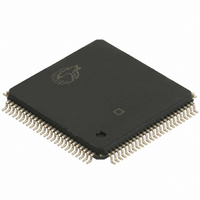
CY7C67300-100AXI Cypress Semiconductor Corp, CY7C67300-100AXI Datasheet - Page 93

CY7C67300-100AXI
Manufacturer Part Number
CY7C67300-100AXI
Description
IC USB HOST/PERIPH CNTRL 100LQFP
Manufacturer
Cypress Semiconductor Corp
Series
EZ-Host™r
Type
Host Programmable Embedded USBr
Datasheet
1.CY7C67300-100AXI.pdf
(99 pages)
Specifications of CY7C67300-100AXI
Package / Case
100-LQFP
Applications
USB Host/Peripheral Controller
Core Processor
CY16
Program Memory Type
ROM (8 kB)
Controller Series
CY7C673xx
Ram Size
16K x 8
Interface
SPI Serial, USB, HPI
Number Of I /o
32
Voltage - Supply
3 V ~ 3.6 V
Operating Temperature
-40°C ~ 85°C
Mounting Type
Surface Mount
Maximum Operating Temperature
+ 85 C
Minimum Operating Temperature
- 40 C
Mounting Style
SMD/SMT
Operating Temperature Range
- 40 C to + 85 C
Supply Current
80 mA
Operating Supply Voltage
3.3 V
Lead Free Status / RoHS Status
Lead free / RoHS Compliant
For Use With
CY4640 - KIT MASS STORAGE REF DESIGNCY3663 - KIT DEV EZ-OTG/EZ-HOST
Lead Free Status / Rohs Status
Lead free / RoHS Compliant
Other names
428-1865
CY7C67300-100AXI
CY7C67300-100AXI
Available stocks
Company
Part Number
Manufacturer
Quantity
Price
Company:
Part Number:
CY7C67300-100AXI
Manufacturer:
ATMEL
Quantity:
210
Company:
Part Number:
CY7C67300-100AXI
Manufacturer:
CYPRESS
Quantity:
246
Company:
Part Number:
CY7C67300-100AXI
Manufacturer:
Cypress Semiconductor Corp
Quantity:
10 000
Part Number:
CY7C67300-100AXI
Manufacturer:
CYPRESS
Quantity:
20 000
Company:
Part Number:
CY7C67300-100AXIT
Manufacturer:
Cypress Semiconductor Corp
Quantity:
10 000
Table 142. Register Summary (continued)
Document #: 38-08015 Rev. *J
R/W
R/W
R/W
R/W
R/W
R/W
R/W
R/W
R
R/W
R/W
R/W
R/W
W
R/W
R/W
R/W
R/W
-
R/W
R/W
R/W
R/W
R/W
R/W
R/W
Address Register
0xC00C
0xC098
0: 0xC010
1: 0xC012
0xC014
1: 0xC018
2: 0xC01A
0: 0xC01E
1: 0xC024
0: 0xC020
1: 0xC026
0: 0xC022
1: 0xC028
0xC038
0xC03A
0xC03C
0xC03E
0xC048
0xC04A
0xC04C
0xC04E
0xC050-0
xC06E
0xC070
0xC072
0xC074
0xC076
0xC078
0xC07A
0xC07C
0xC00E
Watchdog Timer
Interrupt Enable
OTG Control
Timer n
Breakpoint
Extended Page n Map
GPIO n Output Data
GPIO n Input Data
GPIO n Direction
Upper Address Enable
External Memory Control
USB Diagnostic
Memory Diagnostic
IDE Mode
IDE Start Address
IDE Stop Address
IDE Control
IDE PIO Port
HSS Control
HSS Baud Rate
HSS Transmit Gap
HSS Data
HSS Receive Address
HSS Receive Counter
HSS Transmit Address
Bit 15
Bit 7
Reserved...
...Reserved
Reserved
HSS
Interrupt
Enable
Reserved
D+ Pulldown
Enable
Count...
...Count
Address...
...Address
Address...
...Address
Data...
...Data
Data...
...Data
Direction Select...
...Direction Select
Reserved
Reserved
Reserved
XROM
Width Select
Port 2B
Diagnostic
Enable
...Reserved
Reserved
Reserved
Reserved...
...Reserved
Address...
... Address
Address...
...Address
Reserved...
...Reserved
HSS
Enable
Transmit Done
Interrupt Flag
Reserved
...Baud
Reserved
Transmit Gap Select
Reserved
Data
Address...
...Address
Reserved
...Counter
Address..
...Address
Bit 14
Bit 6
In Mailbox
Interrupt
Enable
D– Pull-down
Enable
XROM
Wait Select
Port 2A
Diagnostic
Enable
Pull-down
Enable
RTS
Polarity
Select
Receive Done
Interrupt Flag
Bit 13
Bit 5
Timeout
Flag
Out Mailbox
Interrupt
Enable
VBUS
Pull-up
Enable
Reserved
XRAM
Merge Enable
Port 1B
Diagnostic
Enable
LS Pull-up
Enable
CTS
Polarity
Select
One
Stop Bit
Bit 12
Bit 4
Period
Select
OTG Interrupt
Enable
Reserved
Receive
Disable
XROM
Merge Enable
Port 1A
Diagnostic
Enable
FS Pull-up
Enable
XOFF
Transmit
Ready
HSS Baud...
Bit 11
Bit 3
SPI Interrupt
Enable
UART
Interrupt
Enable
Charge Pump
Enable
Upper
Address
Enable
XMEM
Width Select
XRAM
Width Select
Reserved...
Reserved
Reserved
Direction
Select
XOFF
Enable
Packet Mode
Select
Bit 10
Bit 2
Lock
Enable
Reserved
GPIO
Interrupt
Enable
VBUS
Discharge
Enable
OTG Data
Status
Reserved
XMEM
Wait Select
XRAM
Wait Select
Force Select
Memory
Arbitration
Select
Mode Select
IDE Interrupt
Enable
CTS
Enable
Receive
Overflow Flag
Bit 9
Bit 1
WDT
Enable
Host/Device 2
Interrupt
Enable
Timer 1
Interrupt
Enable
D+
Pull-up
Enable
ID
Status
Done
Flag
Receive
Interrupt
Enable
Receive Pack-
et Ready Flag
Counter...
Bit 8
Bit 0
Reset
Strobe
Host/Device 1
Interrupt
Enable
Timer 0
Interrupt
Enable
D–
Pull-up
Enable
VBUS Valid
Flag
Monitor
Enable
IDE
Enable
Done
Interrupt
Enable
Receive
Ready Flag
CY7C67300
Page 93 of 99
Default High
Default Low
0000 0000
0000 0000
0000 0000
0001 0000
0000 0000
0000 0xxx
1111 1111
1111 1111
0000 0000
0000 0000
0000 0000
0000 0000
0000 0000
0000 0000
0000 0000
0000 0000
0000 0000
0000 0000
xxxx xxxx
xxxx 0xxx
xxxx xxxx
xxxx xxxx
0000 0000
0000 0000
0000 0000
0000 0000
0000 0000
0000 0000
0000 0000
0000 0000
0000 0000
0000 0000
0000 0000
0000 0000
0000 0000
0000 0000
0000 0000
0001 0111
0000 0000
0000 1001
xxxx xxxx
xxxx xxxx
0000 0000
0000 0000
0000 0000
0000 0000
0000 0000
0000 0000
[+] Feedback


