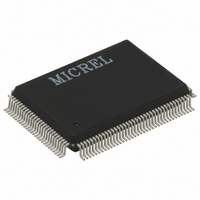
KSZ8842-16MQL Micrel Inc, KSZ8842-16MQL Datasheet - Page 33

KSZ8842-16MQL
Manufacturer Part Number
KSZ8842-16MQL
Description
IC SWITCH 10/100 16BIT 128PQFP
Manufacturer
Micrel Inc
Datasheets
1.KSZ8841-PMQLI.pdf
(2 pages)
2.KSZ8842-16MQL.pdf
(126 pages)
3.KSZ8842-16MQL.pdf
(141 pages)
Specifications of KSZ8842-16MQL
Data Rate
100Mbps
Controller Type
Ethernet Switch Controller
Interface
PCI
Voltage - Supply
3.1 V ~ 3.5 V
Operating Temperature
0°C ~ 70°C
Mounting Type
Surface Mount
Package / Case
128-MQFP, 128-PQFP
No. Of Ports
1
Ethernet Type
IEEE 802.3u
Supply Current
122mA
Supply Voltage Range
3.1V To 3.5V
Operating Temperature Range
0°C To +70°C
Digital Ic Case Style
QFP
No. Of
RoHS Compliant
Number Of Primary Switch Ports
2
Internal Memory Buffer Size
32
Operating Supply Voltage (typ)
3.3V
Fiber Support
Yes
Integrated Led Drivers
Yes
Phy/transceiver Interface
MII
Power Supply Type
Analog/Digital
Package Type
PQFP
Data Rate (typ)
10/100Mbps
Vlan Support
Yes
Operating Temperature (max)
70C
Operating Temperature (min)
0C
Pin Count
128
Mounting
Surface Mount
Jtag Support
No
Operating Supply Voltage (max)
3.5V
Operating Supply Voltage (min)
3.1V
Operating Temperature Classification
Commercial
Interface Type
PCI
Rohs Compliant
Yes
Lead Free Status / RoHS Status
Lead free / RoHS Compliant
For Use With
576-1634 - BOARD EVALUATION KSZ8842-16MQL
Current - Supply
-
Lead Free Status / RoHS Status
Compliant, Lead free / RoHS Compliant
Other names
576-1478-5
Available stocks
Company
Part Number
Manufacturer
Quantity
Price
Company:
Part Number:
KSZ8842-16MQLI
Manufacturer:
MICREL
Quantity:
760
Synchronous Interface
For synchronous transfers, the synchronous dedicated signals CYCLEN, SWR, and RDYRTNN will toggle but the
asynchronous dedicated signals RDN and WRN are de-asserted and stay at the same logic level throughout the entire
synchronous transfer.
The synchronous interface mainly supports two applications, one for VLBus-like and the other for EISA-like (DMA type C)
burst transfers. The VLBus-like interface supports only single-data transfer. The pin option VLBUSN determines if it is a
VLBus-like or EISA-like burst transfer – if VLBUSN = 0, the interface is for VLBus-like transfer; if VLBUSN = 1, the
interface is for EISA-like burst transfer.
Summary
Figure 11 shows the mapping from ISA-like, EISA-like and VLBus-like transactions to the switch’s BIU.
Figure 12 shows the connection for different data bus sizes.
Note: For the 8-bit data bus mode, the internal inverter is enabled and connected between BE0N and BE1N, so even
address will enable the BE0N and odd address will enable the BE1N.
Micrel Confidential
November 2005
The typical example for this application is for an embedded processor having a central decoder on the system board
or within the processor. Connecting the chip select (CS) from system/host to DATACSN bypasses the local device
decoder. When the DATACSN is asserted, it only allows access to the Data Register in 32 bits and BE3N, BE2N,
BE1N, and BE0N are ignored as shown in the Figure 18. No other registers can be accessed by asserting DATACSN.
The data transfer is the same as in the first case. Independent of the type of asynchronous interface used. To insert a
wait state, the BIU will assert ARDY to prolong the cycle.
For VLBus-like transfer interface (VLBUSN = 0):
This interface is used in an architecture in which the device’s local decoder is utilized; that is, the BIU decodes latched
A[15:4] and qualifies with AEN (Address Enable) to determine if the switch is the intended target. No burst is
supported in this application. The M/nIO signal connection in VLBus is routed to AEN. The CYCLEN in this application
is used to sample the SWR signal when it is asserted. Usually, CYCLEN is one clock delay of ADSN. There is a
handshaking process to end the cycle of VLBus-like transfers. When the KSZ8842M is ready to finish the cycle, it
asserts SRDYN
the read data. The KSZ8842M holds the read data until RDYRTNN is asserted. The timing waveform is shown in
Figure 22 and Figure 23.
For EISA-like burst transfer interface (VLBUSN = 1):
The SWR is connected to IORC# in EISA to indicate the burst read and CYCLEN is connected to IOWC# in EISA to
indicate the burst write. Note that in this application, both the system/host/memory and KSZ8842M are capable of
inserting wait states. For system/host/memory to insert a wait state, assert the RDYRTNN signal; for the KSZ8842M
to insert the wait state, assert the SRDYN signal. The timing waveform is shown in Figure 20 and Figure 21.
.
The system/host acknowledges SRDYN by asserting RDYRTNN after the system/host has latched
33
KSZ8842-16/32 MQL/MVL
Rev. 1.4


