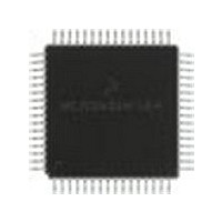
MC68HC705X32CFU Freescale Semiconductor, MC68HC705X32CFU Datasheet - Page 143

MC68HC705X32CFU
Manufacturer Part Number
MC68HC705X32CFU
Description
Manufacturer
Freescale Semiconductor
Datasheet
1.MC68HC705X32CFU.pdf
(232 pages)
Specifications of MC68HC705X32CFU
Cpu Family
HC05
Device Core Size
8b
Frequency (max)
4MHz
Interface Type
SCI
Program Memory Type
EPROM
Program Memory Size
32KB
Total Internal Ram Size
528Byte
# I/os (max)
32
Number Of Timers - General Purpose
1
Operating Supply Voltage (typ)
5V
Operating Supply Voltage (max)
5.5V
Operating Supply Voltage (min)
4.5V
On-chip Adc
8-chx8-bit
Instruction Set Architecture
CISC
Operating Temp Range
-40C to 85C
Operating Temperature Classification
Industrial
Mounting
Surface Mount
Pin Count
64
Package Type
PQFP
Lead Free Status / Rohs Status
Supplier Unconfirmed
Available stocks
Company
Part Number
Manufacturer
Quantity
Price
Part Number:
MC68HC705X32CFU4
Manufacturer:
FREESCALE
Quantity:
20 000
- Current page: 143 of 232
- Download datasheet (6Mb)
10.2.1
Each potential interrupt source is assigned a priority level, which means that if more than one
interrupt is pending at the same time, the processor will service the one with the highest priority
first. For example, if both an external interrupt and a timer interrupt are pending after an instruction
execution, the external interrupt is serviced first.
Table 10-2
interrupt processing flow.
10.2.2
The software interrupt (SWI) is an executable instruction and a nonmaskable interrupt: it is
executed regardless of the state of the I-bit in the CCR. If the I-bit is zero (interrupts enabled), SWI
is executed after interrupts that were pending when the SWI was fetched, but before interrupts
generated after the SWI was fetched. The SWI interrupt service routine address is specified by the
contents of memory locations $3FFC and $3FFD.
10.2.3
If the interrupt mask bit in the CCR is set, all maskable interrupts (internal and external) are
masked. Clearing the I-bit allows interrupt processing to occur.
Note:
MC68HC05X16
External interrupt (IRQ) or WOI
The internal interrupt latch is cleared in the first part of the interrupt service routine;
therefore, one external interrupt pulse could be latched and serviced as soon as the I-bit
is cleared.
shows the relative priority of all the possible interrupt sources.
Software interrupt (SWI)
Timer output compares
Serial communications
Interrupt priorities
Nonmaskable software interrupt (SWI)
Maskable hardware interrupts
Timer input captures
Freescale Semiconductor, Inc.
Timer overflow
interface (SCI)
Source
MCAN
For More Information On This Product,
Reset
Go to: www.freescale.com
Table 10-2 Interrupt priorities
RESETS AND INTERRUPTS
Register
SCSR
CINT
TSR
TSR
TSR
—
—
—
OCF1, OCF2
WIF,OIF,EIF,
ICF1, ICF2
OR, RDRF,
TDRE, TC,
TIF, RIF
Flags
IDLE
TOF
—
—
—
Vector address Priority
$3FFC, $3FFD
$3FFE, $3FFF
$3FFA, $3FFB
$3FF8, $3FF9
$3FF6, $3FF7
$3FF4, $3FF5
$3FF2, $3FF3
$3FF0, $3FF1
Figure 10-4
highest
lowest
shows the
10-9
10
Related parts for MC68HC705X32CFU
Image
Part Number
Description
Manufacturer
Datasheet
Request
R
Part Number:
Description:
Manufacturer:
Freescale Semiconductor, Inc
Datasheet:
Part Number:
Description:
Manufacturer:
Freescale Semiconductor, Inc
Datasheet:
Part Number:
Description:
Manufacturer:
Freescale Semiconductor, Inc
Datasheet:
Part Number:
Description:
Manufacturer:
Freescale Semiconductor, Inc
Datasheet:
Part Number:
Description:
Manufacturer:
Freescale Semiconductor, Inc
Datasheet:
Part Number:
Description:
Manufacturer:
Freescale Semiconductor, Inc
Datasheet:
Part Number:
Description:
Manufacturer:
Freescale Semiconductor, Inc
Datasheet:
Part Number:
Description:
Manufacturer:
Freescale Semiconductor, Inc
Datasheet:
Part Number:
Description:
Manufacturer:
Freescale Semiconductor, Inc
Datasheet:
Part Number:
Description:
Manufacturer:
Freescale Semiconductor, Inc
Datasheet:
Part Number:
Description:
Manufacturer:
Freescale Semiconductor, Inc
Datasheet:
Part Number:
Description:
Manufacturer:
Freescale Semiconductor, Inc
Datasheet:
Part Number:
Description:
Manufacturer:
Freescale Semiconductor, Inc
Datasheet:
Part Number:
Description:
Manufacturer:
Freescale Semiconductor, Inc
Datasheet:
Part Number:
Description:
Manufacturer:
Freescale Semiconductor, Inc
Datasheet:


