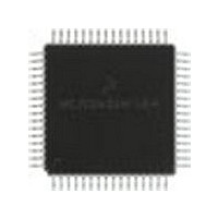
MC68HC705X32CFU Freescale Semiconductor, MC68HC705X32CFU Datasheet - Page 170

MC68HC705X32CFU
Manufacturer Part Number
MC68HC705X32CFU
Description
Manufacturer
Freescale Semiconductor
Datasheet
1.MC68HC705X32CFU.pdf
(232 pages)
Specifications of MC68HC705X32CFU
Cpu Family
HC05
Device Core Size
8b
Frequency (max)
4MHz
Interface Type
SCI
Program Memory Type
EPROM
Program Memory Size
32KB
Total Internal Ram Size
528Byte
# I/os (max)
32
Number Of Timers - General Purpose
1
Operating Supply Voltage (typ)
5V
Operating Supply Voltage (max)
5.5V
Operating Supply Voltage (min)
4.5V
On-chip Adc
8-chx8-bit
Instruction Set Architecture
CISC
Operating Temp Range
-40C to 85C
Operating Temperature Classification
Industrial
Mounting
Surface Mount
Pin Count
64
Package Type
PQFP
Lead Free Status / Rohs Status
Supplier Unconfirmed
Available stocks
Company
Part Number
Manufacturer
Quantity
Price
Part Number:
MC68HC705X32CFU4
Manufacturer:
FREESCALE
Quantity:
20 000
- Current page: 170 of 232
- Download datasheet (6Mb)
13
13.2
L
Seating
Plane
-C-
E
- A -
C
Dim.
G
A
B
C
D
E
F
H
K
J
L
H
13.90
13.90
2.067
0.067
0.130
49
64
Min.
0.30
2.00
0.30
0.50
12.00 REF
0.80 BSC
1
48
64-pin quad flat pack (QFP) mechanical dimensions
G
Case No. 840C
14.10
14.10
2.457
0.250
0.230
Max.
0.45
2.40
0.66
Freescale Semiconductor, Inc.
- D -
64 lead QFP
0.20 M C A – B S D S
0.05 A – B
0.20 M H A – B S D S
—
Figure 13-2 64-pin QFP mechanical dimensions
L
A
S
1. Datum Plane –H– is located at bottom of lead and is coincident with
2. Datums A–B and –D to be determined at Datum Plane –H–.
3. Dimensions S and V to be determined at seating plane –C–.
4. Dimensions A and B do not include mould protrusion. Allowable
5. Dimension D does not include dambar protrusion. Allowable
6. Dimensions and tolerancing per ANSI Y 14.5M, 1982.
7. All dimensions in mm.
For More Information On This Product,
the lead where the lead exits the plastic body at the bottom of the
parting line.
mould protrusion is 0.25mm per side. Dimensions A and B do
include mould mismatch and are determined at Datum Plane –H–.
dambar protrusion shall be 0.08 total in excess of the D dimension
at maximum material condition. Dambar cannot be located on the
lower radius or the foot.
Detail “A”
Go to: www.freescale.com
33
16
MECHANICAL DATA
32
17
M
M
-H-
- B -
Notes
Detail “C”
Datum
Plane
B
V
J
W
0.20 M C A – B S D S
Dim.
W
M
N
Q
R
U
P
S
T
V
X
U
Section B–B
B
B
F
D
X
0.130
16.20
16.20
Min.
0.13
1.10
Detail “A”
K
0.042 NOM
5
2
9
MC68HC05X16
0.40 BSC
0.20 REF
N
- A, B, D -
0.170
16.60
16.60
Max.
0.30
1.30
R
10
15
8
T
Metal
Base
Q
Rev. 1
P
Related parts for MC68HC705X32CFU
Image
Part Number
Description
Manufacturer
Datasheet
Request
R
Part Number:
Description:
Manufacturer:
Freescale Semiconductor, Inc
Datasheet:
Part Number:
Description:
Manufacturer:
Freescale Semiconductor, Inc
Datasheet:
Part Number:
Description:
Manufacturer:
Freescale Semiconductor, Inc
Datasheet:
Part Number:
Description:
Manufacturer:
Freescale Semiconductor, Inc
Datasheet:
Part Number:
Description:
Manufacturer:
Freescale Semiconductor, Inc
Datasheet:
Part Number:
Description:
Manufacturer:
Freescale Semiconductor, Inc
Datasheet:
Part Number:
Description:
Manufacturer:
Freescale Semiconductor, Inc
Datasheet:
Part Number:
Description:
Manufacturer:
Freescale Semiconductor, Inc
Datasheet:
Part Number:
Description:
Manufacturer:
Freescale Semiconductor, Inc
Datasheet:
Part Number:
Description:
Manufacturer:
Freescale Semiconductor, Inc
Datasheet:
Part Number:
Description:
Manufacturer:
Freescale Semiconductor, Inc
Datasheet:
Part Number:
Description:
Manufacturer:
Freescale Semiconductor, Inc
Datasheet:
Part Number:
Description:
Manufacturer:
Freescale Semiconductor, Inc
Datasheet:
Part Number:
Description:
Manufacturer:
Freescale Semiconductor, Inc
Datasheet:
Part Number:
Description:
Manufacturer:
Freescale Semiconductor, Inc
Datasheet:


