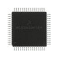
MC68HC705X32CFU Freescale Semiconductor, MC68HC705X32CFU Datasheet - Page 63

MC68HC705X32CFU
Manufacturer Part Number
MC68HC705X32CFU
Description
Manufacturer
Freescale Semiconductor
Datasheet
1.MC68HC705X32CFU.pdf
(232 pages)
Specifications of MC68HC705X32CFU
Cpu Family
HC05
Device Core Size
8b
Frequency (max)
4MHz
Interface Type
SCI
Program Memory Type
EPROM
Program Memory Size
32KB
Total Internal Ram Size
528Byte
# I/os (max)
32
Number Of Timers - General Purpose
1
Operating Supply Voltage (typ)
5V
Operating Supply Voltage (max)
5.5V
Operating Supply Voltage (min)
4.5V
On-chip Adc
8-chx8-bit
Instruction Set Architecture
CISC
Operating Temp Range
-40C to 85C
Operating Temperature Classification
Industrial
Mounting
Surface Mount
Pin Count
64
Package Type
PQFP
Lead Free Status / Rohs Status
Supplier Unconfirmed
Available stocks
Company
Part Number
Manufacturer
Quantity
Price
Part Number:
MC68HC705X32CFU4
Manufacturer:
FREESCALE
Quantity:
20 000
- Current page: 63 of 232
- Download datasheet (6Mb)
The MCAN includes all hardware modules necessary to implement the CAN transfer layer, which
represents the kernel of the CAN bus protocol as defined by BOSCH GmbH, the originators of the
CAN specification. For full details of the CAN protocol please refer to the published specifications.
Up to the message level, the MCAN is totally compatible with the full CAN implementation.
Functional differences are related to the object layer only. Whereas a full CAN controller provides
dedicated hardware for handling a set of messages, the MCAN is restricted to receiving and/or
transmitting messages on a message by message basis.
The MCAN will never initiate an overload frame. If the MCAN starts to receive a valid message
(one that passes the acceptance filter) and there is no receive buffer available for it then the
overrun flag in the CPU status register will be set. The MCAN will respond to overload frames
generated by other CAN nodes, as required by the CAN protocol. A summary of all the MCAN
frame formats is given in
shown in
MC68HC05X16
Figure
MOTOROLA CAN MODULE (MCAN)
Microprocessor related logic
Freescale Semiconductor, Inc.
5-1.
management
Interface
For More Information On This Product,
Transmit
Receive
Receive
buffer 0
buffer 1
logic
buffer
Figure 5-2
MOTOROLA CAN MODULE (MCAN)
Go to: www.freescale.com
Figure 5-1 MCAN block diagram
for reference. A diagram of the major blocks of the MCAN is
5
management
Error
logic
Bus line related logic
Transceive
Bit stream
processor
Bit timing
logic
logic
interface
logic
Line
MCAN
bus
line
5-1
5
Related parts for MC68HC705X32CFU
Image
Part Number
Description
Manufacturer
Datasheet
Request
R
Part Number:
Description:
Manufacturer:
Freescale Semiconductor, Inc
Datasheet:
Part Number:
Description:
Manufacturer:
Freescale Semiconductor, Inc
Datasheet:
Part Number:
Description:
Manufacturer:
Freescale Semiconductor, Inc
Datasheet:
Part Number:
Description:
Manufacturer:
Freescale Semiconductor, Inc
Datasheet:
Part Number:
Description:
Manufacturer:
Freescale Semiconductor, Inc
Datasheet:
Part Number:
Description:
Manufacturer:
Freescale Semiconductor, Inc
Datasheet:
Part Number:
Description:
Manufacturer:
Freescale Semiconductor, Inc
Datasheet:
Part Number:
Description:
Manufacturer:
Freescale Semiconductor, Inc
Datasheet:
Part Number:
Description:
Manufacturer:
Freescale Semiconductor, Inc
Datasheet:
Part Number:
Description:
Manufacturer:
Freescale Semiconductor, Inc
Datasheet:
Part Number:
Description:
Manufacturer:
Freescale Semiconductor, Inc
Datasheet:
Part Number:
Description:
Manufacturer:
Freescale Semiconductor, Inc
Datasheet:
Part Number:
Description:
Manufacturer:
Freescale Semiconductor, Inc
Datasheet:
Part Number:
Description:
Manufacturer:
Freescale Semiconductor, Inc
Datasheet:
Part Number:
Description:
Manufacturer:
Freescale Semiconductor, Inc
Datasheet:


