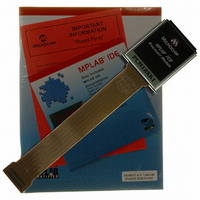
PCM18XK1 Microchip Technology, PCM18XK1 Datasheet - Page 31

PCM18XK1
Manufacturer Part Number
PCM18XK1
Description
MODULE PROC PIC18F8680,6680,8565
Manufacturer
Microchip Technology
Datasheet
1.PCM18XK1.pdf
(496 pages)
Specifications of PCM18XK1
Accessory Type
Processor Module
Lead Free Status / RoHS Status
Not applicable / Not applicable
For Use With/related Products
ICE2000
For Use With
ICE2000 - EMULATOR MPLAB-ICE 2000 POD
Lead Free Status / Rohs Status
Lead free / RoHS Compliant
- Current page: 31 of 496
- Download datasheet (9Mb)
If the main oscillator is configured for HS mode with
PLL active, an oscillator start-up time (T
additional PLL time-out (T
out is typically 2 ms and allows the PLL to lock to the
main oscillator frequency. A timing diagram, indicating
the transition from the Timer1 oscillator to the main
oscillator for HS-PLL mode, is shown in Figure 2-10.
FIGURE 2-10:
FIGURE 2-11:
2004 Microchip Technology Inc.
Program Counter
Program Counter
Note:
Internal System
Internal System
(OSCCON<0>)
(OSCCON<0>)
PLL Clock
PLL Clock
T1OSI
T1OSI
OSC1
OSC1
Clock
Clock
Input
T
Input
SCS
SCS
OST
= 1024 T
Q4
PC
Q4
PC
TIMING FOR TRANSITION BETWEEN TIMER1 AND OSC1
(HS WITH PLL ACTIVE, SCS1 = 1)
TIMING FOR TRANSITION BETWEEN TIMER1 AND OSC1
(EC WITH PLL ACTIVE, SCS1 = 1)
OSC
PLL
(drawing not to scale).
Q1
Q1
) will occur. The PLL time-
T
OST
T
PLL
OST
T
PLL
PIC18F6585/8585/6680/8680
) plus an
T
PC + 2
T
PC + 2
OSC
OSC
1
1
If the main oscillator is configured for EC mode with PLL
active, only the PLL time-out (T
time-out is typically 2 ms and allows the PLL to lock to
the main oscillator frequency. A timing diagram, indicat-
ing the transition from the Timer1 oscillator to the main
oscillator for EC with PLL active, is shown in Figure 2-11.
2
2
3
3
T
T
SCS
SCS
T
4
T
4
T
T
1
1
P
P
5
5
6
6
7
7
Q1 Q2 Q3 Q4
Q1 Q2 Q3 Q4
8
8
PLL
) will occur. The PLL
DS30491C-page 29
Q1 Q2
Q1 Q2
PC + 4
PC + 4
Q3
Q3
Q4
Q4
Related parts for PCM18XK1
Image
Part Number
Description
Manufacturer
Datasheet
Request
R

Part Number:
Description:
Manufacturer:
Microchip Technology Inc.
Datasheet:

Part Number:
Description:
Manufacturer:
Microchip Technology Inc.
Datasheet:

Part Number:
Description:
Manufacturer:
Microchip Technology Inc.
Datasheet:

Part Number:
Description:
Manufacturer:
Microchip Technology Inc.
Datasheet:

Part Number:
Description:
Manufacturer:
Microchip Technology Inc.
Datasheet:

Part Number:
Description:
Manufacturer:
Microchip Technology Inc.
Datasheet:

Part Number:
Description:
Manufacturer:
Microchip Technology Inc.
Datasheet:

Part Number:
Description:
Manufacturer:
Microchip Technology Inc.
Datasheet:


