STEVAL-IFS006V1 STMicroelectronics, STEVAL-IFS006V1 Datasheet - Page 114
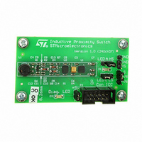
STEVAL-IFS006V1
Manufacturer Part Number
STEVAL-IFS006V1
Description
BOARD EVAL 8BIT MICRO + TDE1708
Manufacturer
STMicroelectronics
Datasheets
1.TDE1708DFT.pdf
(14 pages)
2.STEVAL-IFS006V1.pdf
(136 pages)
3.STEVAL-IFS006V1.pdf
(4 pages)
Specifications of STEVAL-IFS006V1
Design Resources
STEVAL-IFS006V1 Bill of Material
Sensor Type
Proximity
Interface
I²C
Voltage - Supply
6 V ~ 48 V
Embedded
Yes, MCU, 8-Bit
Utilized Ic / Part
ST7FLITEUS5, TDE1708
Processor To Be Evaluated
ST7LITEUS5
Data Bus Width
8 bit
Operating Supply Voltage
6 V to 48 V
Silicon Manufacturer
ST Micro
Silicon Core Number
TDE1708DFT
Kit Application Type
Sensing - Touch / Proximity
Application Sub Type
Proximity Switch
Kit Contents
Board
Rohs Compliant
Yes
Lead Free Status / RoHS Status
Lead free / RoHS Compliant
Sensitivity
-
Sensing Range
-
Lead Free Status / Rohs Status
Lead free / RoHS Compliant
Other names
497-6403
STEVAL-IFS006V1
STEVAL-IFS006V1
Available stocks
Company
Part Number
Manufacturer
Quantity
Price


Electrical characteristics
114/136
Refer also to
conditions.
Table 65.
1. T
2. Data based on characterization results, not tested in production.
3. The I
4. The R
5. To guarantee the reset of the device, a minimum pulse has to be applied to the RESET pin. All short pulses
Figure 61. RESET pin protection when LVD is enabled
1. When the LVD is enabled, it is recommended not to connect a pull-up resistor or capacitor. A 10nF pull-
2. When using the LVD:
3. In case a capacitive power supply is used, it is recommended to connect a 1MΩ pull-down resistor to the
t
w(RSTL)out
t
t
Symbol
h(RSTL)in
g(RSTL)in
of I
between V
applied on RESET pin with a duration below t
down capacitor is required to filter noise on the reset line.
- Check that all recommendations related to ICCCLK and reset circuit have been applied (see caution in
Table 2
- Check that the power supply is properly decoupled (100nF + 10µF close to the MCU). Refer to AN1709
and AN2017. If this cannot be done, it is recommended to put a 100nF + 1MΩ pull-down on the RESET
pin.
- The capacitors connected on the RESET pin and also the power supply are key to avoid any startup
marginality. In most cases, steps 1 and 2 above are sufficient for a robust solution. Otherwise: replace
10nF pull-down on the RESET pin with a 5µF to 20µF capacitor.”
RESET pin to discharge any residual voltage induced by the capacitive effect of the power supply (this will
add 5µA to the power consumption of the MCU).
R
V
V
EXTERNAL
V
V
A
hys
ON
OL
RESET
IH
IL
= -40°C to 125°C, unless otherwise specified.
IO
IO
(I/O ports and control pins) must not exceed I
ON
current sunk must always respect the absolute maximum rating specified in
and text above)
pull-up equivalent resistor is based on a resistive transistor. Specified for voltages on RESET pin
ILmax
Input low level voltage
Input high level voltage
Schmitt trigger voltage
hysteresis
Output low level voltage
Pull-up equivalent resistor
Generated reset pulse duration
External reset pulse hold time
Filtered glitch duration
Asynchronous RESET pin characteristics
Section 11.2.1: Illegal opcode reset
Required
and V
0.01μF
(2)
DD.
Parameter
1MΩ
Optional
(note 3)
(3)
(4)
(5)
h(RSTL)in
V
V
Internal reset sources
DD
IN
V
VSS
R
DD
ON
=
=5 V I
V
can be ignored.
Filter
.
Conditions
SS
for more details on illegal opcode reset
V
V
IO
DD
DD
GENERATOR
=+2 mA
=5 V
=3 V
PULSE
(1)
ST7LITEUS2, ST7LITEUS5
0.7V
V
Min
0.3
30
20
SS
DD
-
Table 44
WATCHDOG
ILLEGAL OPCODE
LVD RESET
200
90
90
Typ
50
2
(2)
(2)
INTERNAL
RESET
and the sum
0.3V
V
ST7XXX
Max
400
DD
0.3
70
DD
+
5)
Unit
mV
kΩ
μs
μs
ns
V
V
Related parts for STEVAL-IFS006V1
Image
Part Number
Description
Manufacturer
Datasheet
Request
R

Part Number:
Description:
BOARD EVAL SPZB260 MOD FOR STR9
Manufacturer:
STMicroelectronics
Datasheet:

Part Number:
Description:
BOARD EVAL EXTENSION SN250
Manufacturer:
STMicroelectronics
Datasheet:

Part Number:
Description:
BOARD EVAL AB-54003L-512
Manufacturer:
STMicroelectronics
Datasheet:

Part Number:
Description:
BOARD REF DESIGN RF DMOS PWR AMP
Manufacturer:
STMicroelectronics
Datasheet:

Part Number:
Description:
BOARD EVAL PWR AMP AB-84008L-470
Manufacturer:
STMicroelectronics
Datasheet:

Part Number:
Description:
BOARD EVAL FOR STM32F103XX
Manufacturer:
STMicroelectronics
Datasheet:

Part Number:
Description:
BOARD EVAL AB-54003L-512
Manufacturer:
STMicroelectronics
Datasheet:

Part Number:
Description:
BOARD SMART PLUG STM32 SPZB260PR
Manufacturer:
STMicroelectronics
Datasheet:

Part Number:
Description:
BOARD DEMO BLUETOOTH SPBT2532C2
Manufacturer:
STMicroelectronics
Datasheet:
Part Number:
Description:
ZIGBEE USB DONGLE EVAL KIT
Manufacturer:
STMicroelectronics
Datasheet:
Part Number:
Description:
STMicroelectronics [RIPPLE-CARRY BINARY COUNTER/DIVIDERS]
Manufacturer:
STMicroelectronics
Datasheet:
Part Number:
Description:
STMicroelectronics [LIQUID-CRYSTAL DISPLAY DRIVERS]
Manufacturer:
STMicroelectronics
Datasheet:

Part Number:
Description:
BOARD EVAL FOR MEMS SENSORS
Manufacturer:
STMicroelectronics
Datasheet: