STEVAL-IFS006V1 STMicroelectronics, STEVAL-IFS006V1 Datasheet - Page 14
STEVAL-IFS006V1
Manufacturer Part Number
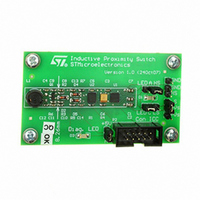
STEVAL-IFS006V1
Description
BOARD EVAL 8BIT MICRO + TDE1708
Manufacturer
STMicroelectronics
Datasheets
1.TDE1708DFT.pdf
(14 pages)
2.STEVAL-IFS006V1.pdf
(136 pages)
3.STEVAL-IFS006V1.pdf
(4 pages)
Specifications of STEVAL-IFS006V1
Design Resources
STEVAL-IFS006V1 Bill of Material
Sensor Type
Proximity
Interface
I²C
Voltage - Supply
6 V ~ 48 V
Embedded
Yes, MCU, 8-Bit
Utilized Ic / Part
ST7FLITEUS5, TDE1708
Processor To Be Evaluated
ST7LITEUS5
Data Bus Width
8 bit
Operating Supply Voltage
6 V to 48 V
Silicon Manufacturer
ST Micro
Silicon Core Number
TDE1708DFT
Kit Application Type
Sensing - Touch / Proximity
Application Sub Type
Proximity Switch
Kit Contents
Board
Rohs Compliant
Yes
Lead Free Status / RoHS Status
Lead free / RoHS Compliant
Sensitivity
-
Sensing Range
-
Lead Free Status / Rohs Status
Lead free / RoHS Compliant
Other names
497-6403
STEVAL-IFS006V1
STEVAL-IFS006V1
Available stocks
Company
Part Number
Manufacturer
Quantity
Price


Pin description
Table 2.
1. After a reset, the multiplexed PA3/RESET pin will act as RESET. To configure this pin as output (Port A3), write 55h to
14/136
1
2
3
4
5
6
7
8
Pin
no.
MUXCR0 and AAh to MUXCR1. For further details, please refer to
V
PA5/AIN4/CLKIN
PA4/AIN3/MCO
PA3/RESET
PA2/AIN2/LTIC
PA1/AIN1/
ICCCLK
PA0/AIN0/ATPW
M/ICCDATA
V
DD
SS
Pin name
Legend/abbreviations for
Type: I = input, O = output, S = supply
In/Output level: C
Output level: HS = High sink (on N-buffer only)
Port and control configuration
●
●
The RESET configuration of each pin is shown in bold which is valid as long as the device is
in reset state.
Device pin description
(1)
Input: float = floating, wpu = weak pull-up, int = interrupt, ana = analog
Output: OD = open drain, PP = push-pull
O
O
O
O
O
O
S
S
I/
I/
I/
I/
I/
C
C
C
C
C
Level
T
T
T
T
T
T
HS
HS
HS
HS
HS
= CMOS 0.3 V
X
X
X
X
X
Table 2
X
Input
Port/control
ei4
ei3
ei2
ei1
ei0
DD
X
X
X
X
X
/0.7 V
Output
X
X
X
X
X
X
DD
Section 6.5 on page
X Port A5
X Port A4
X Port A3
X Port A2
X Port A1
X Port A0
with input trigger
Main power supply
Ground
function
reset)
(after
Main
Analog input 4 or External Clock
Input
Analog input 3 or main clock output
RESET
Analog input 2 or Lite Timer Input
Capture
Analog input 1 or In Circuit
Communication Clock
Caution: During normal operation
this pin must be pulled-up, internally
or externally (external pull-up of 10k
mandatory in noisy environment).
This is to avoid entering I
unexpectedly during a reset. In the
application, even if the pin is
configured as output, any reset will
put it back in pull-up
Analog input 0 or Auto-Reload
Timer PWM or In Circuit
Communication Data
37.
ST7LITEUS2, ST7LITEUS5
(1)
Alternate function
2
C mode
Related parts for STEVAL-IFS006V1
Image
Part Number
Description
Manufacturer
Datasheet
Request
R

Part Number:
Description:
BOARD EVAL SPZB260 MOD FOR STR9
Manufacturer:
STMicroelectronics
Datasheet:

Part Number:
Description:
BOARD EVAL EXTENSION SN250
Manufacturer:
STMicroelectronics
Datasheet:

Part Number:
Description:
BOARD EVAL AB-54003L-512
Manufacturer:
STMicroelectronics
Datasheet:

Part Number:
Description:
BOARD REF DESIGN RF DMOS PWR AMP
Manufacturer:
STMicroelectronics
Datasheet:

Part Number:
Description:
BOARD EVAL PWR AMP AB-84008L-470
Manufacturer:
STMicroelectronics
Datasheet:

Part Number:
Description:
BOARD EVAL FOR STM32F103XX
Manufacturer:
STMicroelectronics
Datasheet:

Part Number:
Description:
BOARD EVAL AB-54003L-512
Manufacturer:
STMicroelectronics
Datasheet:

Part Number:
Description:
BOARD SMART PLUG STM32 SPZB260PR
Manufacturer:
STMicroelectronics
Datasheet:

Part Number:
Description:
BOARD DEMO BLUETOOTH SPBT2532C2
Manufacturer:
STMicroelectronics
Datasheet:
Part Number:
Description:
ZIGBEE USB DONGLE EVAL KIT
Manufacturer:
STMicroelectronics
Datasheet:
Part Number:
Description:
STMicroelectronics [RIPPLE-CARRY BINARY COUNTER/DIVIDERS]
Manufacturer:
STMicroelectronics
Datasheet:
Part Number:
Description:
STMicroelectronics [LIQUID-CRYSTAL DISPLAY DRIVERS]
Manufacturer:
STMicroelectronics
Datasheet:

Part Number:
Description:
BOARD EVAL FOR MEMS SENSORS
Manufacturer:
STMicroelectronics
Datasheet: