STEVAL-IFS006V1 STMicroelectronics, STEVAL-IFS006V1 Datasheet - Page 66
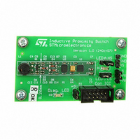
STEVAL-IFS006V1
Manufacturer Part Number
STEVAL-IFS006V1
Description
BOARD EVAL 8BIT MICRO + TDE1708
Manufacturer
STMicroelectronics
Datasheets
1.TDE1708DFT.pdf
(14 pages)
2.STEVAL-IFS006V1.pdf
(136 pages)
3.STEVAL-IFS006V1.pdf
(4 pages)
Specifications of STEVAL-IFS006V1
Design Resources
STEVAL-IFS006V1 Bill of Material
Sensor Type
Proximity
Interface
I²C
Voltage - Supply
6 V ~ 48 V
Embedded
Yes, MCU, 8-Bit
Utilized Ic / Part
ST7FLITEUS5, TDE1708
Processor To Be Evaluated
ST7LITEUS5
Data Bus Width
8 bit
Operating Supply Voltage
6 V to 48 V
Silicon Manufacturer
ST Micro
Silicon Core Number
TDE1708DFT
Kit Application Type
Sensing - Touch / Proximity
Application Sub Type
Proximity Switch
Kit Contents
Board
Rohs Compliant
Yes
Lead Free Status / RoHS Status
Lead free / RoHS Compliant
Sensitivity
-
Sensing Range
-
Lead Free Status / Rohs Status
Lead free / RoHS Compliant
Other names
497-6403
STEVAL-IFS006V1
STEVAL-IFS006V1
Available stocks
Company
Part Number
Manufacturer
Quantity
Price


On-chip peripherals
10.1.3
Note:
66/136
Figure 30. Lite timer block diagram
Functional description
The value of the 13-bit counter cannot be read or written by software. After an MCU reset, it
starts incrementing from 0 at a frequency of f
counter rolls over from 1F39h to 00h. If f
counter overflow events is 1 ms. This period can be doubled by setting the TB bit in the
LTCSR register.
When the timer overflows, the TBF bit is set by hardware and an interrupt request is
generated if the TBIE is set. The TBF bit is cleared by software reading the LTCSR register.
Watchdog
The watchdog is enabled using the WDGE bit. The normal watchdog timeout is 2 ms (@
fosc = 8 MHz), after which it then generates a reset.
To prevent this watchdog reset occurring, software must set the WDGD bit. The WDGD bit is
cleared by hardware after t
regular intervals to prevent a watchdog reset occurring. Refer to
If the watchdog is not enabled immediately after reset, the first watchdog timeout will be
shorter than 2ms, because this period is counted starting from reset. Moreover, if a 2ms
period has already elapsed after the last MCU reset, the watchdog reset will take place as
soon as the WDGE bit is set. For these reasons, it is recommended to enable the watchdog
immediately after reset or else to set the WDGD bit before the WGDE bit so a watchdog
reset will not occur for at least 2 ms.
Software can use the timebase feature to set the WDGD bit at 1 or 2 ms intervals.
LTIC
f
OSC
LTICR
13-bit UPCOUNTER
INPUT CAPTURE
REGISTER
8-bit
8 MSB
WDG
7
LTCSR
ICIE
. This means that software must write to the WDGD bit at
f
f
LTIMER
LTIMER
/2
ICF
TB
1
0
OSC
To 12-bit AT TImer
f
WDG
Timebase
1 or 2 ms
(@ 8MHz
f
OSC
TBIE
OSC
= 8 MHz, then the time period between two
)
. A counter overflow event occurs when the
TBF
WDG
RF
WATCHDOG
LTIC INTERRUPT REQUEST
LTTB INTERRUPT REQUEST
WDGE
WDGD
ST7LITEUS2, ST7LITEUS5
Figure
0
WATCHDOG RESET
31.
Related parts for STEVAL-IFS006V1
Image
Part Number
Description
Manufacturer
Datasheet
Request
R

Part Number:
Description:
BOARD EVAL SPZB260 MOD FOR STR9
Manufacturer:
STMicroelectronics
Datasheet:

Part Number:
Description:
BOARD EVAL EXTENSION SN250
Manufacturer:
STMicroelectronics
Datasheet:

Part Number:
Description:
BOARD EVAL AB-54003L-512
Manufacturer:
STMicroelectronics
Datasheet:

Part Number:
Description:
BOARD REF DESIGN RF DMOS PWR AMP
Manufacturer:
STMicroelectronics
Datasheet:

Part Number:
Description:
BOARD EVAL PWR AMP AB-84008L-470
Manufacturer:
STMicroelectronics
Datasheet:

Part Number:
Description:
BOARD EVAL FOR STM32F103XX
Manufacturer:
STMicroelectronics
Datasheet:

Part Number:
Description:
BOARD EVAL AB-54003L-512
Manufacturer:
STMicroelectronics
Datasheet:

Part Number:
Description:
BOARD SMART PLUG STM32 SPZB260PR
Manufacturer:
STMicroelectronics
Datasheet:

Part Number:
Description:
BOARD DEMO BLUETOOTH SPBT2532C2
Manufacturer:
STMicroelectronics
Datasheet:
Part Number:
Description:
ZIGBEE USB DONGLE EVAL KIT
Manufacturer:
STMicroelectronics
Datasheet:
Part Number:
Description:
STMicroelectronics [RIPPLE-CARRY BINARY COUNTER/DIVIDERS]
Manufacturer:
STMicroelectronics
Datasheet:
Part Number:
Description:
STMicroelectronics [LIQUID-CRYSTAL DISPLAY DRIVERS]
Manufacturer:
STMicroelectronics
Datasheet:

Part Number:
Description:
BOARD EVAL FOR MEMS SENSORS
Manufacturer:
STMicroelectronics
Datasheet: