STEVAL-IFS006V1 STMicroelectronics, STEVAL-IFS006V1 Datasheet - Page 19
STEVAL-IFS006V1
Manufacturer Part Number
STEVAL-IFS006V1
Description
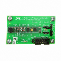
BOARD EVAL 8BIT MICRO + TDE1708
Manufacturer
STMicroelectronics
Datasheets
1.TDE1708DFT.pdf
(14 pages)
2.STEVAL-IFS006V1.pdf
(136 pages)
3.STEVAL-IFS006V1.pdf
(4 pages)
Specifications of STEVAL-IFS006V1
Design Resources
STEVAL-IFS006V1 Bill of Material
Sensor Type
Proximity
Interface
I²C
Voltage - Supply
6 V ~ 48 V
Embedded
Yes, MCU, 8-Bit
Utilized Ic / Part
ST7FLITEUS5, TDE1708
Processor To Be Evaluated
ST7LITEUS5
Data Bus Width
8 bit
Operating Supply Voltage
6 V to 48 V
Silicon Manufacturer
ST Micro
Silicon Core Number
TDE1708DFT
Kit Application Type
Sensing - Touch / Proximity
Application Sub Type
Proximity Switch
Kit Contents
Board
Rohs Compliant
Yes
Lead Free Status / RoHS Status
Lead free / RoHS Compliant
Sensitivity
-
Sensing Range
-
Lead Free Status / Rohs Status
Lead free / RoHS Compliant
Other names
497-6403
STEVAL-IFS006V1
STEVAL-IFS006V1
Available stocks
Company
Part Number
Manufacturer
Quantity
Price


ST7LITEUS2, ST7LITEUS5
4.3.2
4.4
●
●
Depending on the ICP driver code downloaded in RAM, FLASH memory programming can
be fully customized (number of bytes to program, program locations, or selection of the
serial communication interface for downloading).
In application programming (IAP)
This mode uses an IAP driver program previously programmed in Sector 0 by the user (in
ICP mode).
This mode is fully controlled by user software. This allows it to be adapted to the user
application, (user-defined strategy for entering programming mode, choice of
communications protocol used to fetch the data to be stored etc).
IAP mode can be used to program any memory areas except Sector 0, which is write/erase
protected to allow recovery in case errors occur during the programming operation.
I
ICP needs a minimum of 4 and up to 6 pins to be connected to the programming tool. These
pins are:
●
●
●
●
●
●
Refer to
If the ICCCLK or ICCDATA pins are only used as outputs in the application, no signal
isolation is necessary. As soon as the programming tool is plugged to the board, even if an
I
application. If they are used as inputs by the application, isolation such as a serial resistor
has to be implemented in case another device forces the signal. Refer to the programming
tool documentation for recommended resistor values.
During the ICP session, the programming tool must control the RESET pin. This can lead to
conflicts between the programming tool and the application reset circuit if it drives more than
5 mA at high level (push pull output or pull-up resistor<1 kΩ). A schottky diode can be used
to isolate the application RESET circuit in this case. When using a classical RC network with
R>1 kΩ or a reset management IC with open drain output and pull-up resistor>1 kΩ, no
additional components are needed. In all cases the user must ensure that no external reset
is generated by the application during the I
The use of Pin 7 of the I
pin must be connected when using most ST programming tools (it is used to monitor the
application power supply). Please refer to the programming tool manual.
2
2
C session is not in progress, the ICCCLK and ICCDATA pins are not available for the
C interface
the I
interface.
Download ICP driver code in RAM from the ICCDATA pin
Execute ICP driver code in RAM to program the FLASH memory
RESET: device reset
V
ICCCLK: I
ICCDATA: I
CLKIN: main clock input for external source
V
SS
DD
Figure 6
: device power supply ground
: application board power supply
2
C protocol routine. This routine enables the ST7 to receive bytes from the I
2
C output serial clock pin
2
C input serial data pin
for a description of the I
2
C connector depends on the programming tool architecture. This
2
C interface.
2
C session.
Flash program memory
2
19/136
C
Related parts for STEVAL-IFS006V1
Image
Part Number
Description
Manufacturer
Datasheet
Request
R

Part Number:
Description:
BOARD EVAL SPZB260 MOD FOR STR9
Manufacturer:
STMicroelectronics
Datasheet:

Part Number:
Description:
BOARD EVAL EXTENSION SN250
Manufacturer:
STMicroelectronics
Datasheet:

Part Number:
Description:
BOARD EVAL AB-54003L-512
Manufacturer:
STMicroelectronics
Datasheet:

Part Number:
Description:
BOARD REF DESIGN RF DMOS PWR AMP
Manufacturer:
STMicroelectronics
Datasheet:

Part Number:
Description:
BOARD EVAL PWR AMP AB-84008L-470
Manufacturer:
STMicroelectronics
Datasheet:

Part Number:
Description:
BOARD EVAL FOR STM32F103XX
Manufacturer:
STMicroelectronics
Datasheet:

Part Number:
Description:
BOARD EVAL AB-54003L-512
Manufacturer:
STMicroelectronics
Datasheet:

Part Number:
Description:
BOARD SMART PLUG STM32 SPZB260PR
Manufacturer:
STMicroelectronics
Datasheet:

Part Number:
Description:
BOARD DEMO BLUETOOTH SPBT2532C2
Manufacturer:
STMicroelectronics
Datasheet:
Part Number:
Description:
ZIGBEE USB DONGLE EVAL KIT
Manufacturer:
STMicroelectronics
Datasheet:
Part Number:
Description:
STMicroelectronics [RIPPLE-CARRY BINARY COUNTER/DIVIDERS]
Manufacturer:
STMicroelectronics
Datasheet:
Part Number:
Description:
STMicroelectronics [LIQUID-CRYSTAL DISPLAY DRIVERS]
Manufacturer:
STMicroelectronics
Datasheet:

Part Number:
Description:
BOARD EVAL FOR MEMS SENSORS
Manufacturer:
STMicroelectronics
Datasheet: