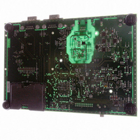
AT91RM3400-DK Atmel, AT91RM3400-DK Datasheet - Page 13

AT91RM3400-DK
Manufacturer Part Number
AT91RM3400-DK
Description
KIT DEV FOR AT91RM3400
Manufacturer
Atmel
Series
AT91SAM Smart ARMr
Type
MCUr
Datasheets
1.AT91RM3400-DK.pdf
(461 pages)
2.AT91RM3400-DK.pdf
(2 pages)
3.AT91RM3400-DK.pdf
(25 pages)
Specifications of AT91RM3400-DK
Contents
Evaluation Board, Software and Documentation
Processor To Be Evaluated
AT91RM3400
Data Bus Width
32 bit
Interface Type
RS-232, USB
For Use With/related Products
AT91RM3400
Lead Free Status / RoHS Status
Contains lead / RoHS non-compliant
- Current page: 13 of 461
- Download datasheet (6Mb)
Peripheral
Multiplexing on
PIO Lines
PIO Controller A Multiplexing
Table 2. Multiplexing on PIO Controller A
1790A–ATARM–11/03
I/O Line
PA10
PA11
PA12
PA13
PA14
PA15
PA16
PA17
PA18
PA19
PA20
PA21
PA22
PA23
PA24
PA25
PA0
PA1
PA2
PA3
PA4
PA5
PA6
PA7
PA8
PA9
Peripheral A
PIO Controller A
MCCDA
NPCS0
NPCS1
NPCS2
NPCS3
TWCK
MCCK
SPCK
RXD0
RXD1
DSR1
DCD1
RXD2
MISO
MOSI
TXD0
SCK0
CTS0
RTS0
TXD1
RTS1
CTS1
DTR1
TXD2
TWD
RI1
The AT91RM3400 features two PIO controllers (PIOA and PIOB) that allow multiplexing of the
I/O lines of the peripheral set.
Each PIO controller controls up to 32 lines. Each line can be assigned to one of the two
peripheral functions, A or B.
The tables in the following paragraphs define how the I/O lines of the peripheral A and B are
multiplexed on the PIO controllers A and B. The two columns “Function” and “Comments”
have been inserted for the user’s own comments; they may be used to track how pins are
defined in an application.
Peripheral B
TCLK0
TCLK1
TCLK2
TIOA0
TIOB0
TIOA1
TIOB1
TIOA2
TIOB2
PCK0
PCK1
SCK1
SCK2
PCK2
PCK3
RTS0
RTS1
–
–
–
–
–
–
–
–
–
Function
Application Usage
Comments
AT91RM3400
13
Related parts for AT91RM3400-DK
Image
Part Number
Description
Manufacturer
Datasheet
Request
R

Part Number:
Description:
DEV KIT FOR AVR/AVR32
Manufacturer:
Atmel
Datasheet:

Part Number:
Description:
INTERVAL AND WIPE/WASH WIPER CONTROL IC WITH DELAY
Manufacturer:
ATMEL Corporation
Datasheet:

Part Number:
Description:
Low-Voltage Voice-Switched IC for Hands-Free Operation
Manufacturer:
ATMEL Corporation
Datasheet:

Part Number:
Description:
MONOLITHIC INTEGRATED FEATUREPHONE CIRCUIT
Manufacturer:
ATMEL Corporation
Datasheet:

Part Number:
Description:
AM-FM Receiver IC U4255BM-M
Manufacturer:
ATMEL Corporation
Datasheet:

Part Number:
Description:
Monolithic Integrated Feature Phone Circuit
Manufacturer:
ATMEL Corporation
Datasheet:

Part Number:
Description:
Multistandard Video-IF and Quasi Parallel Sound Processing
Manufacturer:
ATMEL Corporation
Datasheet:

Part Number:
Description:
High-performance EE PLD
Manufacturer:
ATMEL Corporation
Datasheet:

Part Number:
Description:
8-bit Flash Microcontroller
Manufacturer:
ATMEL Corporation
Datasheet:

Part Number:
Description:
2-Wire Serial EEPROM
Manufacturer:
ATMEL Corporation
Datasheet:


