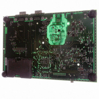
AT91RM3400-DK Atmel, AT91RM3400-DK Datasheet - Page 328

AT91RM3400-DK
Manufacturer Part Number
AT91RM3400-DK
Description
KIT DEV FOR AT91RM3400
Manufacturer
Atmel
Series
AT91SAM Smart ARMr
Type
MCUr
Datasheets
1.AT91RM3400-DK.pdf
(461 pages)
2.AT91RM3400-DK.pdf
(2 pages)
3.AT91RM3400-DK.pdf
(25 pages)
Specifications of AT91RM3400-DK
Contents
Evaluation Board, Software and Documentation
Processor To Be Evaluated
AT91RM3400
Data Bus Width
32 bit
Interface Type
RS-232, USB
For Use With/related Products
AT91RM3400
Lead Free Status / RoHS Status
Contains lead / RoHS non-compliant
- Current page: 328 of 461
- Download datasheet (6Mb)
SSC Receive Clock Mode Register
Name:
Access Type:
• CKS: Receive Clock Selection
• CKO: Receive Clock Output Mode Selection
• CKI: Receive Clock Inversion
0: The data and the Frame Sync signal are sampled on Receive Clock falling edge.
1: The data and the Frame Sync signal are shifted out on Receive Clock rising edge.
CKI does not affects the RK output clock signal.
• START: Receive Start Selection
328
0x8-0xF
START
0x0
0x1
0x2
0x3
0x4
0x5
0x6
0x7
0x2-0x7
31
23
15
–
7
–
CKO
CKS
0x0
0x1
0x0
0x1
0x2
0x3
AT91RM3400
Continuous, as soon as the receiver is enabled, and immediately after the end of
transfer of the previous data.
Transmit Start
Detection of a low level on RF input
Detection of a high level on RF input
Detection of a falling edge on RF input
Detection of a rising edge on RF input
Detection of any level change on RF input
Detection of any edge on RF input
Reserved
Receive Start
SSC_RCMR
Read/Write
Receive Clock Output Mode
None
Continuous Receive Clock
Reserved
Selected Receive Clock
Divided Clock
TK Clock Signal
RK Pin
Reserved
30
22
14
–
6
–
CKI
29
21
13
–
5
28
20
12
–
4
PERIOD
STTDLY
CKO
27
19
11
3
26
18
10
2
START
25
17
9
1
Input-only
CKS
RK pin
Output
1790A–ATARM–11/03
24
16
8
0
Related parts for AT91RM3400-DK
Image
Part Number
Description
Manufacturer
Datasheet
Request
R

Part Number:
Description:
DEV KIT FOR AVR/AVR32
Manufacturer:
Atmel
Datasheet:

Part Number:
Description:
INTERVAL AND WIPE/WASH WIPER CONTROL IC WITH DELAY
Manufacturer:
ATMEL Corporation
Datasheet:

Part Number:
Description:
Low-Voltage Voice-Switched IC for Hands-Free Operation
Manufacturer:
ATMEL Corporation
Datasheet:

Part Number:
Description:
MONOLITHIC INTEGRATED FEATUREPHONE CIRCUIT
Manufacturer:
ATMEL Corporation
Datasheet:

Part Number:
Description:
AM-FM Receiver IC U4255BM-M
Manufacturer:
ATMEL Corporation
Datasheet:

Part Number:
Description:
Monolithic Integrated Feature Phone Circuit
Manufacturer:
ATMEL Corporation
Datasheet:

Part Number:
Description:
Multistandard Video-IF and Quasi Parallel Sound Processing
Manufacturer:
ATMEL Corporation
Datasheet:

Part Number:
Description:
High-performance EE PLD
Manufacturer:
ATMEL Corporation
Datasheet:

Part Number:
Description:
8-bit Flash Microcontroller
Manufacturer:
ATMEL Corporation
Datasheet:

Part Number:
Description:
2-Wire Serial EEPROM
Manufacturer:
ATMEL Corporation
Datasheet:


