AT91RM3400-DK Atmel, AT91RM3400-DK Datasheet - Page 297
AT91RM3400-DK
Manufacturer Part Number
AT91RM3400-DK
Description
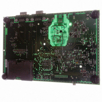
KIT DEV FOR AT91RM3400
Manufacturer
Atmel
Series
AT91SAM Smart ARMr
Type
MCUr
Datasheets
1.AT91RM3400-DK.pdf
(461 pages)
2.AT91RM3400-DK.pdf
(2 pages)
3.AT91RM3400-DK.pdf
(25 pages)
Specifications of AT91RM3400-DK
Contents
Evaluation Board, Software and Documentation
Processor To Be Evaluated
AT91RM3400
Data Bus Width
32 bit
Interface Type
RS-232, USB
For Use With/related Products
AT91RM3400
Lead Free Status / RoHS Status
Contains lead / RoHS non-compliant


• SYNC: Synchronous Mode Select
0 = USART operates in Asynchronous Mode.
1 = USART operates in Synchronous Mode
• PAR: Parity Type
• NBSTOP: Number of Stop Bits
• CHMODE: Channel Mode
• MSBF: Bit Order
0 = Least Significant Bit is sent/received first.
1 = Most Significant Bit is sent/received first.
• MODE9: 9-bit Character Length
0 = CHRL defines character length.
1 = 9-bit character length.
• CKLO: Clock Output Select
0 = The USART does not drive the SCK pin.
1 = The USART drives the SCK pin if USCLKS does not select the external clock SCK.
• OVER: Oversampling Mode
0 = 16x Oversampling.
1 = 8x Oversampling.
1790A–ATARM–11/03
0
0
1
1
0
0
1
1
CHMODE
NBSTOP
0
0
0
0
1
1
0
1
0
1
0
1
0
1
PAR
0
0
1
1
0
1
Asynchronous (SYNC = 0)
1 stop bit
1.5 stop bits
2 stop bits
Reserved
Mode Description
Normal Mode
Automatic Echo. Receiver input is connected to the TXD pin.
Local Loopback. Transmitter output is connected to the Receiver Input..
Remote Loopback. RXD pin is internally connected to the TXD pin.
0
1
0
1
x
x
Parity Type
Even parity
Odd parity
Parity forced to 0 (Space)
Parity forced to 1 (Mark)
No parity
Multi-drop mode
Synchronous (SYNC = 1)
1 stop bit
Reserved
2 stop bits
Reserved
AT91RM3400
297
Related parts for AT91RM3400-DK
Image
Part Number
Description
Manufacturer
Datasheet
Request
R

Part Number:
Description:
DEV KIT FOR AVR/AVR32
Manufacturer:
Atmel
Datasheet:

Part Number:
Description:
INTERVAL AND WIPE/WASH WIPER CONTROL IC WITH DELAY
Manufacturer:
ATMEL Corporation
Datasheet:
Part Number:
Description:
Low-Voltage Voice-Switched IC for Hands-Free Operation
Manufacturer:
ATMEL Corporation
Datasheet:
Part Number:
Description:
MONOLITHIC INTEGRATED FEATUREPHONE CIRCUIT
Manufacturer:
ATMEL Corporation
Datasheet:
Part Number:
Description:
AM-FM Receiver IC U4255BM-M
Manufacturer:
ATMEL Corporation
Datasheet:
Part Number:
Description:
Monolithic Integrated Feature Phone Circuit
Manufacturer:
ATMEL Corporation
Datasheet:
Part Number:
Description:
Multistandard Video-IF and Quasi Parallel Sound Processing
Manufacturer:
ATMEL Corporation
Datasheet:
Part Number:
Description:
High-performance EE PLD
Manufacturer:
ATMEL Corporation
Datasheet:
Part Number:
Description:
8-bit Flash Microcontroller
Manufacturer:
ATMEL Corporation
Datasheet:
Part Number:
Description:
2-Wire Serial EEPROM
Manufacturer:
ATMEL Corporation
Datasheet: