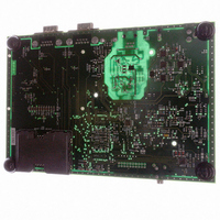
AT91RM3400-DK Atmel, AT91RM3400-DK Datasheet - Page 34

AT91RM3400-DK
Manufacturer Part Number
AT91RM3400-DK
Description
KIT DEV FOR AT91RM3400
Manufacturer
Atmel
Series
AT91SAM Smart ARMr
Type
MCUr
Datasheets
1.AT91RM3400-DK.pdf
(461 pages)
2.AT91RM3400-DK.pdf
(2 pages)
3.AT91RM3400-DK.pdf
(25 pages)
Specifications of AT91RM3400-DK
Contents
Evaluation Board, Software and Documentation
Processor To Be Evaluated
AT91RM3400
Data Bus Width
32 bit
Interface Type
RS-232, USB
For Use With/related Products
AT91RM3400
Lead Free Status / RoHS Status
Contains lead / RoHS non-compliant
- Current page: 34 of 461
- Download datasheet (6Mb)
Debug and Test Pin
Description
Functional Description
Test Pin
Embedded In-circuit
Emulator
34
AT91RM3400
Table 10. Debug and Test Pin List
One dedicated pin, TST, is used to define the device operating mode. The user must
make sure that this pin is tied at low level to ensure normal operating conditions. Other
values associated to this pin are manufacturing test reserved.
ARM7TDMI embedded In-circuit Emulator is supported via the ICE/JTAG port.The inter-
nal state of the ARM7TDMI is examined through a ICE/JTAG port.
The ARM7TDMI processor contains hardware extensions for advanced debugging
features:
•
•
There are three scan chains inside the ARM7TDMI processor that support testing,
debugging, and programming of the Embedded ICE. The scan chains are controlled by
the ICE/JTAG port.
Embedded ICE mode is selected when JTAGSEL is low. It is not possible to switch
directly between ICE and JTAG operations. A chip reset must be performed (NRST)
after JTAGSEL is changed.
For further details on the Embedded In-Circuit-Emulator, see the ARM7TDMI (Rev4)
Technical Reference Manual (DDI0210B).
Pin Name
NRST
TST
TCK
TDI
TDO
TMS
JTAGSEL
DRXD
DTXD
In halt mode, a store-multiple (STM) can be inserted into the instruction pipeline.
This exports the contents of the ARM7TDMI registers. This data can be serially
shifted out without affecting the rest of the system.
In monitor mode, the JTAG interface is used to transfer data between the debugger
and a simple monitor program running on the ARM7TDMI processor.
Function
Microcontroller Reset
Test Mode Select
Test Clock
Test Data In
Test Data Out
Test Mode Select
JTAG Selection
Debug Receive Data
Debug Transmit Data
ICE and JTAG
Debug Unit
Reset/Test
Output
Output
Type
Input
Input
Input
Input
Input
Input
Input
1790A–ATARM–11/03
Active Level
Low
Related parts for AT91RM3400-DK
Image
Part Number
Description
Manufacturer
Datasheet
Request
R

Part Number:
Description:
DEV KIT FOR AVR/AVR32
Manufacturer:
Atmel
Datasheet:

Part Number:
Description:
INTERVAL AND WIPE/WASH WIPER CONTROL IC WITH DELAY
Manufacturer:
ATMEL Corporation
Datasheet:

Part Number:
Description:
Low-Voltage Voice-Switched IC for Hands-Free Operation
Manufacturer:
ATMEL Corporation
Datasheet:

Part Number:
Description:
MONOLITHIC INTEGRATED FEATUREPHONE CIRCUIT
Manufacturer:
ATMEL Corporation
Datasheet:

Part Number:
Description:
AM-FM Receiver IC U4255BM-M
Manufacturer:
ATMEL Corporation
Datasheet:

Part Number:
Description:
Monolithic Integrated Feature Phone Circuit
Manufacturer:
ATMEL Corporation
Datasheet:

Part Number:
Description:
Multistandard Video-IF and Quasi Parallel Sound Processing
Manufacturer:
ATMEL Corporation
Datasheet:

Part Number:
Description:
High-performance EE PLD
Manufacturer:
ATMEL Corporation
Datasheet:

Part Number:
Description:
8-bit Flash Microcontroller
Manufacturer:
ATMEL Corporation
Datasheet:

Part Number:
Description:
2-Wire Serial EEPROM
Manufacturer:
ATMEL Corporation
Datasheet:


