DEMO9S08JM16 Freescale Semiconductor, DEMO9S08JM16 Datasheet - Page 3
DEMO9S08JM16
Manufacturer Part Number
DEMO9S08JM16
Description
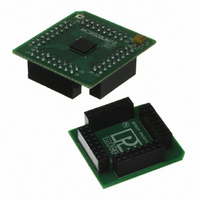
BOARD DEMO FOR JM16 FAMI
Manufacturer
Freescale Semiconductor
Type
MCUr
Datasheets
1.DEMO9S08JM16.pdf
(47 pages)
2.DEMO9S08JM16.pdf
(5 pages)
3.DEMO9S08JM16.pdf
(4 pages)
4.DEMO9S08JM16.pdf
(386 pages)
Specifications of DEMO9S08JM16
Contents
Board with Daughter card, Cable, Documentation, Mini-AB USB Kit
Processor To Be Evaluated
MC9S08JM16
Data Bus Width
8 bit
Interface Type
USB
Silicon Manufacturer
Freescale
Core Architecture
HCS08
Core Sub-architecture
HCS08
Silicon Core Number
MC9S08
Silicon Family Name
Flexis - S08JM
Rohs Compliant
Yes
For Use With/related Products
MC9S08JM16
Lead Free Status / RoHS Status
Lead free / RoHS Compliant


MC9S08JM16 Series Features
8-Bit HCS08 Central Processor Unit (CPU)
Memory Options
Clock Source Options
System Protection
Power-Saving Modes
• 48 MHz HCS08 CPU (central processor unit)
• 24 MHz internal bus frequency
• HC08 instruction set with added BGND instruction
• Background debugging system
• Breakpoint capability to allow single breakpoint
• In-circuit emulator (ICE) debug module containing
• Support for up to 32 interrupt/reset sources
• Up to 16 KB of on-chip in-circuit programmable
• Up to 1 KB of on-chip RAM
• 256 bytes of USB RAM
• Clock source options include crystal, resonator,
• MCG (multi-purpose clock generator) — PLL and
• Optional computer operating properly (COP) reset
• Low-voltage detection with reset or interrupt
• Illegal opcode detection with reset
• Illegal address detection with reset
• Wait plus two stops
setting during in-circuit debugging (plus two more
breakpoints in on-chip debug module)
two comparators and nine trigger modes. Eight
deep FIFO for storing change-of-flow addresses
and event-only data. Debug module supports both
tag and force breakpoints
flash memory with block protection and security
options
external clock
FLL; internal reference clock with trim adjustment
with option to run from independent 1 kHz internal
clock source or the bus clock
Peripherals
Input/Output
Package Options
• USB — USB 2.0 full-speed (12 Mbps) with
• ADC — 8-channel, 12-bit analog-to-digital
• ACMP — Analog comparator with option to
• SCI — Up to two serial communications interface
• SPI — Two 8- or 16-bit selectable serial peripheral
• IIC — Inter-integrated circuit bus module to
• Timers — One 2-channel and one 4-channel
• KBI — 7-pin keyboard interrupt module
• RTC — Real-time counter with binary- or
• Up to 37 general purpose input/output pins
• Software selectable pullup on ports when used as
• Software selectable slew rate control on ports
• Software selectable drive strength on ports when
• Master reset pin and power-on reset (POR)
• Internal pullup on RESET, IRQ, and BKGD/MS
• 48-pin quad flat no-lead (QFN)
• 44-pin low-profile quad flat package (LQFP)
• 32-pin low-profile quad flat package (LQFP)
dedicated on-chip 3.3 V regulator and transceiver;
supporting endpoint 0 and up to 6 additional
endpoints
converter with automatic compare function;
internal temperature sensor
compare to internal reference; operation in stop3
mode
modules with optional 13-bit break; LIN
extensions
interface modules with a receive data buffer
hardware match function
operate at up to 100 kbps with maximum bus
loading; multi-master operation; programmable
slave address; interrupt-driven byte-by-byte data
transfer; broadcast mode; 10-bit addressing
16-bit timer/pulse-width modulator (TPM)
modules; selectable input capture, output
compare, and edge-aligned PWM capability on
each channel. Each timer module may be
configured for buffered, centered PWM (CPWM)
on all channels
decimal-based prescaler
inputs
when used as outputs
used as outputs
pins to reduce customer system cost
Related parts for DEMO9S08JM16
Image
Part Number
Description
Manufacturer
Datasheet
Request
R

Part Number:
Description:
Manufacturer:
Freescale Semiconductor, Inc
Datasheet:
Part Number:
Description:
Manufacturer:
Freescale Semiconductor, Inc
Datasheet:
Part Number:
Description:
Manufacturer:
Freescale Semiconductor, Inc
Datasheet:
Part Number:
Description:
Manufacturer:
Freescale Semiconductor, Inc
Datasheet:
Part Number:
Description:
Manufacturer:
Freescale Semiconductor, Inc
Datasheet:
Part Number:
Description:
Manufacturer:
Freescale Semiconductor, Inc
Datasheet:
Part Number:
Description:
Manufacturer:
Freescale Semiconductor, Inc
Datasheet:
Part Number:
Description:
Manufacturer:
Freescale Semiconductor, Inc
Datasheet:
Part Number:
Description:
Manufacturer:
Freescale Semiconductor, Inc
Datasheet:
Part Number:
Description:
Manufacturer:
Freescale Semiconductor, Inc
Datasheet:
Part Number:
Description:
Manufacturer:
Freescale Semiconductor, Inc
Datasheet:
Part Number:
Description:
Manufacturer:
Freescale Semiconductor, Inc
Datasheet:
Part Number:
Description:
Manufacturer:
Freescale Semiconductor, Inc
Datasheet:
Part Number:
Description:
Manufacturer:
Freescale Semiconductor, Inc
Datasheet:
Part Number:
Description:
Manufacturer:
Freescale Semiconductor, Inc
Datasheet: