AD9549/PCBZ Analog Devices Inc, AD9549/PCBZ Datasheet - Page 30
AD9549/PCBZ
Manufacturer Part Number
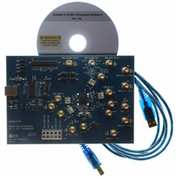
AD9549/PCBZ
Description
BOARD EVALUATION FOR AD9549
Manufacturer
Analog Devices Inc
Datasheet
1.AD9549ABCPZ.pdf
(76 pages)
Specifications of AD9549/PCBZ
Main Purpose
Timing, Clock Generator
Embedded
No
Utilized Ic / Part
AD9549
Primary Attributes
2 Inputs, 2 Outputs, VCO
Secondary Attributes
CMOS, HSTL Output Logic, Graphical User Interface
Lead Free Status / RoHS Status
Lead free / RoHS Compliant


AD9549
Holdover and Reference Switchover State Machine
Figure 37 shows the interplay between the input reference
signals and holdover, as well as the various control signals
and the four states.
State 1 or State 2 is in effect when the device is not in the holdover
condition, and State 3 or State 4 is in effect when the holdover
condition is active. When REFA is selected as the active reference,
State 1 or State 3 is in effect. When REFB is selected as the active
reference, State 2 or State 4 is in effect. A transition between states
depends on the reference switchover and holdover control register
HOLDOVER
HOLDOVER
REFA:
REFB:
HOLDOVER:
FAILA:
FAILB:
VALIDA:
VALIDB:
REFA
REFA
&
&
REFERENCE A SELECTED
REFERENCE B SELECTED
HOLDOVER STATE
REFERENCE A FAILED
REFERENCE B FAILED
REFERENCE A VALIDATED
REFERENCE B VALIDATED
RESET
1
3
FAILA & VALIDB & AUTOREFSEL & OVRDREFPIN
FAILB & VALIDA & AUTOREFSEL & OVRDREFPIN
Figure 37. Holdover State Diagram
ABBREVIATION KEY
Rev. D | Page 30 of 76
OVRDREFPIN:
OVRDHLDPIN:
AUTOREFSEL:
AUTORCOV:
AUTOHOLD:
||:
&:
%:
settings, the logic state of the REFSELECT and HOLDOVER
pins, and the occurrence of certain events (for example, a reference
failure).
The state machine and its relationship to control register and
external pin stimuli are shown in Figure 37. The state machine
generates a derived reference selection and holdover state. The
actual control signal sent to the reference switchover logic and
the holdover logic, however, depends on the control signals
applied to the muxes. The dashed path leading to the REFSELECT
and HOLDOVER pins is active when the automatic mode is
selected for reference selection and/or holdover assertion.
OVERRIDE REF SEL PIN
OVERRIDE HOLDOVER PIN
AUTOMATIC REFERENCE SELECT
AUTOMATIC HOLDOVER RECOVERY
AUTOMATIC HOLDOVER ENTRY
LOGICAL OR
LOGICAL AND
LOGICAL NOT
2
4
HOLDOVER
HOLDOVER
REFB
REFB
&
&
Related parts for AD9549/PCBZ
Image
Part Number
Description
Manufacturer
Datasheet
Request
R


Part Number:
Description:
±1.7g Dual-Axis IMEMS Accelerometer Evaluation Board
Manufacturer:
Analog Devices Inc
Datasheet:

Part Number:
Description:
Inertial Sensor Evaluation System
Manufacturer:
Analog Devices Inc
Datasheet:
Part Number:
Description:
Manufacturer:
Analog Devices Inc
Datasheet:
Part Number:
Description:
Manufacturer:
Analog Devices Inc
Datasheet:
Part Number:
Description:
Manufacturer:
Analog Devices Inc
Datasheet:
Part Number:
Description:
Manufacturer:
Analog Devices Inc
Datasheet:
Part Number:
Description:
Manufacturer:
Analog Devices Inc
Datasheet:
Part Number:
Description:
Manufacturer:
Analog Devices Inc
Datasheet:
Part Number:
Description:
Manufacturer:
Analog Devices Inc
Datasheet:
Part Number:
Description:
Manufacturer:
Analog Devices Inc
Datasheet:
Part Number:
Description:
Manufacturer:
Analog Devices Inc
Datasheet:
Part Number:
Description:
Manufacturer:
Analog Devices Inc
Datasheet: