AD9549/PCBZ Analog Devices Inc, AD9549/PCBZ Datasheet - Page 36
AD9549/PCBZ
Manufacturer Part Number
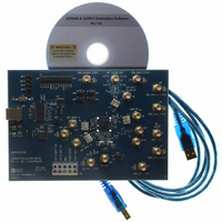
AD9549/PCBZ
Description
BOARD EVALUATION FOR AD9549
Manufacturer
Analog Devices Inc
Datasheet
1.AD9549ABCPZ.pdf
(76 pages)
Specifications of AD9549/PCBZ
Main Purpose
Timing, Clock Generator
Embedded
No
Utilized Ic / Part
AD9549
Primary Attributes
2 Inputs, 2 Outputs, VCO
Secondary Attributes
CMOS, HSTL Output Logic, Graphical User Interface
Lead Free Status / RoHS Status
Lead free / RoHS Compliant


AD9549
The mechanics of performing harmonic spur reduction are shown
in Figure 46. It essentially consists of two additional DDS cores
operating in parallel with the original DDS. This enables the user
to reduce two different harmonic spurs from the second to the
15
ampli-tude control.
The dynamic range of the cancellation signal is further aug-
mented by a gain bit associated with each channel. When this
bit is set, the magnitude of the cancellation signal is doubled by
employing a 1-bit left-shift of the data. However, the shift
operation reduces the granularity of the cancellation signal
magnitude.
Note that the full-scale amplitude of a cancellation spur is
approximately −60 dBc when the gain bit is a Logic 0 and
approximately −54 dBc when the gain bit is a Logic 1.
OUTPUT CLOCK DRIVERS AND 2× FREQUENCY
MULTIPLIER
There are two output drivers provided by the AD9549. The
primary supports differential 1.8 V HSTL output levels while
the secondary supports either 1.8 V or 3.3 V CMOS levels,
depending on whether Pin 37 is driven at 1.8 V or 3.3 V.
The primary differential driver nominally provides an output
voltage with 100 Ω load applied differentially (V
1.8 V). The source impedance of the driver is approximately
100 Ω for most of the output clock period; during transition
between levels, the source impedance reaches a maximum of
about 500 Ω. The driver is designed to support output
th
with nine bits of phase offset control (±π) and eight bits of
TURNING WORD
FREQUENCY
CH1 CANCELLATION PHASE OFFSET
CH2 CANCELLATION PHASE OFFSET
CH1 CANCELLATION MAGNITUDE
CH2 CANCELLATION MAGNITUDE
SYSCLK
48-BIT
(FTW)
CH1 HARMONIC NUMBER
CH2 HARMONIC NUMBER
14
48-BIT ACCUMULATOR
48
48
D
4
9
4
9
8
8
Q
FREQUENCY
GENERATOR
2-CHANNEL
DD
HARMONIC
− V
Figure 46. Spur Reduction Technique
CH2
SS
CH1
19
HARMONIC SPUR CANCELLATION
=
OFFSET
PHASE
14
DDS
Rev. D | Page 36 of 76
19
DDS
SHIFT
CONVERSION
AMPLITUDE
frequencies of up to and beyond the OC-12 network rate of
622.08 MHz.
The output clock can also be powered down by a control bit in
the I/O register map.
Primary 1.8 V Differential HSTL Driver
The DDS produces a sinusoidal clock signal that is sampled at
the system clock rate. This DDS output signal is routed off chip,
where it is passed through an analog filter and brought back on
chip for buffering and, if necessary, frequency doubling. Where
possible, for the best jitter performance, it is recommended that
the upconverter be bypassed.
The 1.8 V HSTL output driver should be ac-coupled, with
100 Ω termination at the destination. The driver design has low
jitter injection for frequencies in the range of 50 MHz to 750 MHz.
Refer to the AC Specifications section for the exact frequency
limits.
2× Frequency Multiplier
The AD9549 can be configured via the I/O register map with an
internal 2× delay-locked loop (DLL) multiplier at the input of
the primary clock driver. The extra octave of frequency gain
allows the AD9549 to provide output clock frequencies that
exceed the range available from the DDS alone. These settings
are found in Register 0x0010 and Register 0x0200.
The input to the DLL consists of the filtered DDS output signal
after it has been squared up by an integrated clock receiver circuit.
The DLL can accept input frequencies in the range of 200 MHz
to 400 MHz.
ANGLE TO
SHIFT
0
1
CORRECTION
0
1
HEADROOM
14
CANCELLATION
ENABLE
SPUR
0
1
CH1 GAIN
CH2 GAIN
14
(14-BIT)
DAC
I-SET
DDS+
DDS–
Related parts for AD9549/PCBZ
Image
Part Number
Description
Manufacturer
Datasheet
Request
R


Part Number:
Description:
±1.7g Dual-Axis IMEMS Accelerometer Evaluation Board
Manufacturer:
Analog Devices Inc
Datasheet:

Part Number:
Description:
Inertial Sensor Evaluation System
Manufacturer:
Analog Devices Inc
Datasheet:
Part Number:
Description:
Manufacturer:
Analog Devices Inc
Datasheet:
Part Number:
Description:
Manufacturer:
Analog Devices Inc
Datasheet:
Part Number:
Description:
Manufacturer:
Analog Devices Inc
Datasheet:
Part Number:
Description:
Manufacturer:
Analog Devices Inc
Datasheet:
Part Number:
Description:
Manufacturer:
Analog Devices Inc
Datasheet:
Part Number:
Description:
Manufacturer:
Analog Devices Inc
Datasheet:
Part Number:
Description:
Manufacturer:
Analog Devices Inc
Datasheet:
Part Number:
Description:
Manufacturer:
Analog Devices Inc
Datasheet:
Part Number:
Description:
Manufacturer:
Analog Devices Inc
Datasheet:
Part Number:
Description:
Manufacturer:
Analog Devices Inc
Datasheet: