DV007004 Microchip Technology, DV007004 Datasheet
DV007004
Specifications of DV007004
Available stocks


Related parts for DV007004

DV007004 Summary of contents
Page 1
... Microchip Technology Inc. ® MPLAB USER’S GUIDE PM3 DS51464C ...
Page 2
... PowerMate, PowerTool, Real ICE, rfLAB, rfPICDEM, Select Mode, Smart Serial, SmartTel, Total Endurance, UNI/O, WiperLock and Zena are trademarks of Microchip Technology Incorporated in the U.S.A. and other countries. SQTP is a service mark of Microchip Technology Incorporated in the U.S.A. All other trademarks mentioned herein are property of their respective companies. ...
Page 3
... Building the Initial Project ............................................................................. 30 3.10 Creating Code ............................................................................................ 31 3.11 Building the Project .................................................................................... 34 3.12 Enabling MPLAB PM3 ................................................................................ 35 3.13 Programming the Device ............................................................................ 36 3.14 Verifying the Programming ......................................................................... 36 3.15 Tutorial Summary ....................................................................................... 36 © 2006 Microchip Technology Inc. Table of Contents MPLAB ® PM3 USER’S GUIDE DS51464C-page iii ...
Page 4
... MPLAB PM3 LCD and Keys ......................................................................... 77 8.3 Start-Up Sequence ....................................................................................... 78 8.4 Main Menu .................................................................................................... 78 8.5 Command Menu ........................................................................................... 82 Chapter 9. MPLAB PM3 Card Reference 9.1 Introduction ................................................................................................... 87 9.2 MPLAB PM3 Card ........................................................................................ 87 9.3 MPLAB PM3 Card Through MPLAB IDE ..................................................... 87 9.4 MPLAB PM3 Card in Stand-alone Mode ...................................................... 97 DS51464C-page iv © 2006 Microchip Technology Inc. ...
Page 5
... B.3 Troubleshooting Operational Problems ..................................................... 108 B.4 Troubleshooting Software .......................................................................... 108 B.5 Common Problems .................................................................................... 110 B.6 Error Messages – PC ................................................................................. 113 B.7 Error Messages – LCD .............................................................................. 114 B.8 Limitations .................................................................................................. 116 Glossary ..................................................................................................................... 117 Index ........................................................................................................................... 131 Worldwide Sales and Service .................................................................................. 134 © 2006 Microchip Technology Inc. DS51464C-page v ...
Page 6
... NOTES: DS51464C-page vi © 2006 Microchip Technology Inc. ...
Page 7
... Document Layout • Conventions Used in this Guide • Warranty Registration • Recommended Reading • The Microchip Web Site • Development Systems Customer Change Notification Service • Customer Support © 2006 Microchip Technology Inc. Preface NOTICE TO CUSTOMERS MPLAB PM3 ® USER’S GUIDE ® ...
Page 8
... MPLAB PM3 Card. • Appendix A. Hardware Specifications – Describes how to connect MPLAB PM3 to a communication port. Provides instructions on cleaning MPLAB PM3 socket modules. • Appendix B. Troubleshooting – Provides information on solving common problems. DS51464C-page 2 ® MCU devices. © 2006 Microchip Technology Inc. ...
Page 9
... N‘Rnnnn Text in angle brackets < > Courier New font: Plain Courier New Italic Courier New Square brackets [ ] Curly brackets and pipe character Ellipses... © 2006 Microchip Technology Inc. Represents Referenced books MPLAB Emphasized text ...is the only compiler... A window the Output window A dialog ...
Page 10
... In-Circuit Serial Programming™ (ICSP™) Guide (DS30277) This document contains helpful design guidelines for successful ICSP programming. It includes application notes on hardware designs and the ICSP programming specifications. DS51464C-page 4 file (an ASCII text file) in the MPLAB IDE\readmes direc- © 2006 Microchip Technology Inc. ...
Page 11
... MPLAB IDE, MPLAB SIM simulator, MPLAB IDE Project Manager and general editing and debugging features. • Programmers – The latest information on Microchip programmers. These include the MPLAB PM3 and PRO MATE Plus and PICkit © 2006 Microchip Technology Inc. ® II device programmers and the PICSTART ™ 1 development programmers. ...
Page 12
... Customers should contact their distributor, representative or field application engineer (FAE) for support. Local sales offices are also available to help customers. A listing of sales offices and locations is included in the back of this document. Technical support is available through the web site at: http://support.microchip.com DS51464C-page 6 © 2006 Microchip Technology Inc. ...
Page 13
... Read code from an unprotected microcontroller into MPLAB IDE’s program memory window for debugging and programming into other devices. • Program unique serialized ID numbers into your firmware using Serial Quick Turn Programming (SQTP • Store environments on an MPLAB PM3 Card. © 2006 Microchip Technology Inc. USER’S GUIDE SM ) files. MPLAB PM3 ® ...
Page 14
... The MPLAB PM3 device programmer is designed, tested and certified to meet the Electromagnetic Compatibility requirements known as the CE compliance directives. These standards, set by the European Union (EU) countries, include limiting radiated emission, reducing susceptibility to radiated emission and reducing susceptibility to Electrostatic Discharge (ESD). DS51464C-page 8 ® MPLAB PM3 DEVICE PROGRAMMER © 2006 Microchip Technology Inc. ...
Page 15
... This document covers the basic setup and operation of the MPLAB PM3 device programmer, but it does not cover all functions of MPLAB IDE. Read the MPLAB IDE documentation to get a full understanding of the features and debug capabilities of MPLAB IDE. © 2006 Microchip Technology Inc. ® microcontroller devices DS51464C-page 9 ...
Page 16
... This can all be accomplished with MPLAB IDE. • Third Party Tools Many other companies have development tools for Microchip products that work with MPLAB IDE. Consult the Microchip web site for additional information. DS51464C-page 10 © 2006 Microchip Technology Inc. ...
Page 17
... Follow the on-screen instructions to install the MPLAB IDE software. • For the Microchip Website www.microchip.com and follow the links to the Development Tools page. - Click the links to the latest MPLAB IDE release and download. © 2006 Microchip Technology Inc. MPLAB PM3 ® USER’S GUIDE ...
Page 18
... USB connectors. All lines on the serial cable are wired straight through. The serial cable is NOT a null modem cable. FIGURE 2-1: Power On Power Off Power Input PWR DS51464C-page 12 NOTICE ® BACK VIEW OF MPLAB PM3 USB Port Serial Port I O USB RS-232 Secure Digital/ Multi-Media Card Port SD-MMC © 2006 Microchip Technology Inc. ...
Page 19
... MPLAB PM3 comes with a proprietary external power supply. 1. Make sure that the power switch on the back of the unit is in the OFF position (see Figure 2-1). 2. Plug the power supply into a power socket and connect the power supply cable to the unit. © 2006 Microchip Technology Inc. NOTICE DS51464C-page 13 ...
Page 20
... The PRO MATE II ICSP socket module is not supported by MPLAB PM3. An 18-inch ICSP cable is included with MPLAB PM3, eliminating the need for an ICSP socket. DS51464C-page 14 ® TOP VIEW OF MPLAB PM3 MPLAB LCD M ESC ENTER Keys/Buttons PM3 ® Device Programmer ICSP Connector Socket Module Connectors © 2006 Microchip Technology Inc. ...
Page 21
... MPLAB IDE”. If you are going to use MPLAB PM3 in Stand-Alone mode, please refer to Chapter 5. “Using MPLAB PM3 in Stand-Alone Mode”. If you are using the MPLAB PM3 Card with either MPLAB IDE or in Stand-Alone mode, also refer to Chapter 6. “Using the MPLAB PM3 Card” © 2006 Microchip Technology Inc. DS51464C-page 15 ...
Page 22
... The MPLAB IDE desktop should look similar to Figure 2-3. FIGURE 2-3: DS51464C-page 16 STATUS LED INDICATIONS Booting up, Programming Failed, Other Error Working/Busy Programming Passed POWER LED On Programmer powered Off Programmer not powered ® MPLAB IDE DESKTOP Condition Condition © 2006 Microchip Technology Inc. ...
Page 23
... After MPLAB PM3 is selected: • The Programmer menu changes to include the MPLAB PM3 Programmer Menu and Settings. • The MPLAB PM3 Toolbar is revealed. • The name of the programmer appears on the status bar. FIGURE 2-4: © 2006 Microchip Technology Inc. SELECT PROGRAMMER MENU DS51464C-page 17 ...
Page 24
... Communications tab. A dialog similar to the one shown in Figure 2-5 will display. FIGURE 2-5: The Communications Port Setup dialog shows the possible PC serial and USB communication ports. Click OK to set the options or Cancel to ignore the changes and close the dialog. DS51464C-page 18 COMMUNICATIONS PORT SETUP DIALOG © 2006 Microchip Technology Inc. ...
Page 25
... Section 2.2 “Installing MPLAB PM3 Software”. FIGURE 2-6: To make sure the port is set up properly, follow the instructions in the “For USB Communications” subsection in Section 2.3.1 “Installing the Communications Cable”. © 2006 Microchip Technology Inc. port USB (Figure 2-6). Click OK. CAUTION ...
Page 26
... MPLAB PM3 Card inserted in the MPLAB PM3 programmer. MPLAB IDE may warn you that your programmer OS Suite is out of date. If you choose, MPLAB IDE will automatically update the necessary files at these warnings. FIGURE 2-8: DS51464C-page 20 SELECT DEVICE DIALOG ENABLE PROGRAMMER © 2006 Microchip Technology Inc. ...
Page 27
... If you are using a socket module, insert the device to be programmed into the MPLAB PM3 socket. Position pin one to be top justified in the socket. Secure the device by pushing down the silver lever on the socket or closing the clamshell. © 2006 Microchip Technology Inc. COMMUNICATIONS ERROR DIALOG DS51464C-page 21 ...
Page 28
... NOTES: DS51464C-page 22 © 2006 Microchip Technology Inc. ...
Page 29
... Adding Files to the Project • Building the Initial Project • Creating Code • Building the Project • Enabling MPLAB PM3 • Programming the Device • Verifying the Programming © 2006 Microchip Technology Inc. Chapter 3. Tutorial MPLAB PM3 ® USER’S GUIDE DS51464C-page 23 ...
Page 30
... Project Wizard. We will use a single assembly file for this project and a linker script. Choose the Project>Project Wizard. FIGURE 3-2: Click on Next> to advance to the next dialog in the Project Wizard. DS51464C-page 24 SELECTING THE DEVICE PROJECT WIZARD WELCOME SCREEN © 2006 Microchip Technology Inc. ...
Page 31
... The next dialog allows you to select the device, which we’ve already done. Make sure that it says PIC18F452 does not, select the PIC18F452 from the drop down menu. Click Next>. FIGURE 3-3: © 2006 Microchip Technology Inc. PROJECT WIZARD – SELECT DEVICE DS51464C-page 25 ...
Page 32
... MPLINK linker executable will be: C:\Program Files\Microchip\MPASM Suite\MPLink.exe If these do not show up correctly, use the Browse button to set them to the proper files in the MPLAB IDE subfolders. FIGURE 3-4: When you are finished, click Next>. DS51464C-page 26 PROJECT WIZARD – SELECT LANGUAGE TOOLS © 2006 Microchip Technology Inc. ...
Page 33
... Step Three of the wizard allows you to name the project and put it into a folder. This sample project will be called 18F452Proj. Using the Browse button, place the project in a folder on the C drive named My Projects. Click Next>. FIGURE 3-5: © 2006 Microchip Technology Inc. PROJECT WIZARD – NAME PROJECT DS51464C-page 27 ...
Page 34
... Press Add>> to move the file name to the right panel, and click on the check box at the start of the line with the file name to enable this file to be copied to our project directory. DS51464C-page 28 PROJECT WIZARD – SELECT TEMPLATE FILE © 2006 Microchip Technology Inc. ...
Page 35
... Next> to finish the Project Wizard. The final screen of the Project Wizard is a summary showing the selected device, the toolsuite and the new project file name. FIGURE 3-8: © 2006 Microchip Technology Inc. PROJECT WIZARD – SELECT LINKER SCRIPT PROJECT WIZARD – SUMMARY DS51464C-page 29 ...
Page 36
... Click back on the 18f452Proj.mcw window to make it the active window. Now, build the project by selecting Project>Build All. The Output window shows the result of the build process as shown in Figure 3-10. FIGURE 3-10: DS51464C-page 30 PROJECT WINDOW INITIAL BUILD RESULTS WINDOW © 2006 Microchip Technology Inc. ...
Page 37
... Configuration bits in a final application. These details can be ignored at this point with focus on writing the code. The new code will be placed in the file at the point after the symbol Main is defined. FIGURE 3-12: © 2006 Microchip Technology Inc. TEMPLATE FILE TEMPLATE FILE – MAIN DS51464C-page 31 ...
Page 38
... Delay0 movlw 0xFF movwf DVAR; set inner delay loop Delay1 decfsz DVAR goto Delay1 decfsz DVAR2 goto Delay0 return The template file should now look like Figure 3-13. FIGURE 3-13: DS51464C-page 32 TEMPLATE FILE – ADD CODE © 2006 Microchip Technology Inc. ...
Page 39
... There are already three variables in this section of the template file, ours can be added at the end using the same format. Each variable is an 8-bit variable, so they only need to reserve 1 byte each. FIGURE 3-14: Add these three lines © 2006 Microchip Technology Inc. TEMPLATE FILE – ADD VARIABLES DS51464C-page 33 ...
Page 40
... This file contains the object code that can be programmed into a PICmicro MCU and debugging information so that source code can be debugged, and source variables can be viewed symbolically in Watch windows. Now that you’ve built your project successfully, you can prepare for programming your device. DS51464C-page 34 BUILD OUTPUT WINDOW © 2006 Microchip Technology Inc. ...
Page 41
... Select View>Program Memory and click on Opcode Hex at the bottom of the window (see Figure 3-16) to view the hex code you’ve just built. You can resize or move the Program Memory window on your display. You may wish to close the Build Results window. FIGURE 3-16: © 2006 Microchip Technology Inc. VIEWING PROGRAM MEMORY DS51464C-page 35 ...
Page 42
... Writing some simple code to send a changing value out an I/O port. Building the project. And finally, programming the PIC18F452 device. These are the essential steps for programming a device with MPLAB IDE and MPLAB PM3. DS51464C-page 36 PROGRAMMING RESULTS © 2006 Microchip Technology Inc. ...
Page 43
... SETUP FOR PROGRAMMING A DEVICE To program a device, you will need: • A hex file to program into the device. • A device to program. Must be blank if non-flash device. (See Section 7.4.7 “Blank Check All”.) © 2006 Microchip Technology Inc. MPLAB PM3 ® USER’S GUIDE ...
Page 44
... Make sure the Configuration Bits window is opened wide enough to view the Settings column (Figure 4-1). FIGURE 4-1: 2. Click on the setting value you wish to change. A down arrow appears to the right of the value. Select a value from the drop-down list box. DS51464C-page 38 CONFIGURATION BITS DIALOG © 2006 Microchip Technology Inc. ...
Page 45
... Select or clear the “Use Unprotected Checksum” check box as needed recommended that if the device is code-protected, this box be checked to use an unprotected checksum. Most devices use this information to calculate the code-protected checksum. 3. Click OK to set the option or click Cancel to cancel the entry. © 2006 Microchip Technology Inc. USER ID MEMORY DIALOG DS51464C-page 39 ...
Page 46
... If you imported your hex file into MPLAB IDE and are using EEPROM data memory, make sure your hex code specifies the start of EEPROM data memory. This needs to be specified for use with programmers. DS51464C-page 40 PROGRAM MEMORY — HEX CODE DISPLAY © 2006 Microchip Technology Inc. ...
Page 47
... Verify that the device is blank (i.e., perform the Blank Check again) before attempting to program it. If the device is EEPROM/Flash, you do not have to erase it before reprogramming it. These devices are electrically erased before programming. © 2006 Microchip Technology Inc. WINDOWED DEVICE DS51464C-page 41 ...
Page 48
... Select this check box if configuration memory programmed. Select this check box if the ID location programmed. Select this check box if the EEPROM data memory programmed. Select this check box if calibration memory to be programmed. Select this check box if the device erased before programming. Description © 2006 Microchip Technology Inc. ...
Page 49
... To program the device, select Programmer>Program. Refer to Section 7.5.3 “SQTP Tab” and Section 7.6.1 “Using SQTP” for more detailed information on SQTP programming. See Section 7.7.1 “Using Hexadecimal Record Formats” for information on hex record formats. © 2006 Microchip Technology Inc. DS51464C-page 43 ...
Page 50
... For information on how to program a specific device using ICSP, consult the programming specification for that device. See the README for MPLAB PM3 for a list of programming specifications of supported devices. Programming specifications may also be found on the Microchip web site at www.microchip.com. DS51464C-page 44 ICSP™ OPTIONS © 2006 Microchip Technology Inc. ...
Page 51
... MPLAB PM3” and Section 4.5.3 “Loading the Hex Code into Pro- gram Memory” for instructions on connecting MPLAB PM3 and downloading a hex file, respectively. Now you are ready to use MPLAB PM3 in Stand-Alone mode. © 2006 Microchip Technology Inc. MPLAB PM3 ® ...
Page 52
... MPLAB PM3 programs the image of the hex file into the microcontroller device con- nected to the programmer. DS51464C-page 46 ® MPLAB PM3 MAIN MENU MPLAB PM3 ® Recently Used Select Device MPLAB PM3 Card Programmer Settings Help © 2006 Microchip Technology Inc. ...
Page 53
... Select “All Functions” to display all of the stand-alone commands that are applicable to programming, reading, verifying and displaying the status of the currently selected device. See Section 8.5.3 “All Functions” for details on each of the options that may be available for the device. © 2006 Microchip Technology Inc. Applied, the V minimum and maximum volt- DD ...
Page 54
... The Help option displays the version number of the MPLAB PM3 OS Suite running on MPLAB PM3 and these submenu options. Refer to Section 8.4.4 “Help” for details. • ICSP Connector Pinout • Status Bar Icons • About DS51464C-page 48 © 2006 Microchip Technology Inc. ...
Page 55
... MPLAB PM3 and program Microchip microcontrollers without ever touching a PC. Topics covered in this chapter include: • MPLAB PM3 Environment • MPLAB PM3 Card © 2006 Microchip Technology Inc. MPLAB PM3 ® USER’S GUIDE DS51464C-page 49 ...
Page 56
... It is the same continuous data chunk that is sent between MPLAB IDE and MPLAB PM3 during a standard operation. Error detection mechanisms are also attached. DS51464C-page 50 LAYOUT OF AN ENVIRONMENT Environment PM3 File (*.pm3) Programmer Settings Optional Device Misc. files SQTP file Memory Image (*.num) *.hex, etc.) (*.bin) (*.txt, © 2006 Microchip Technology Inc. ...
Page 57
... SQTP. (See Section 7.5 “Programmer Settings” for additional information.) When finished, click OK to close the Programmer dialog. 5. Select Programmer>Environment>Save to open the Save Environment dialog (Figure 6-2). FIGURE 6-2: © 2006 Microchip Technology Inc. SAVE ENVIRONMENT DIALOG DS51464C-page 51 ...
Page 58
... From the MPLAB PM3 card menu, select Load an Environment and press <ENTER>. 4. From the PM3CARD:\*.pm3 menu, select your Environment folder and press <ENTER>. 5. Select your Environment.pm3 from the your Environment folder and press <ENTER>. DS51464C-page 52 © 2006 Microchip Technology Inc. ...
Page 59
... Environment stored on the MPLAB PM3 Card • Card Properties – displays the properties of the MPLAB PM3 Card including card capacity, bytes free, bytes used and cluster size For detailed instructions, see Section 9.4 “MPLAB PM3 Card in Stand-alone Mode”. © 2006 Microchip Technology Inc. DS51464C-page 53 ...
Page 60
... NOTES: DS51464C-page 54 © 2006 Microchip Technology Inc. ...
Page 61
... Upgrading the MPLAB PM3 Operating System 7.2 MPLAB PM3 TOOLBAR The MPLAB PM3 toolbar (Figure 7-1) consists of icons for some of the programmer functions and a program statistics display. FIGURE 7-1: © 2006 Microchip Technology Inc. ® MPLAB PM3 TOOLBAR MPLAB PM3 ® ...
Page 62
... Select values for the device Configuration bits. Setting these values will affect both debugger and programmer operation. Select whether to use external memory or not. Also specify external memory range. Enter value into ID memory. Enter default setting for the workspace, debugger, program loading, hot keys and project. Description © 2006 Microchip Technology Inc. ...
Page 63
... Transfer from MPLAB PM3 Establish Communications Load SQTP File About Environment MPLAB PM3 Card Settings © 2006 Microchip Technology Inc. ® MPLAB PM3 MENU Lists the available programmers. Enables the programmer. Disables the programmer. Transfers the hex data file to the programmer and programs the device. Selective programming (e.g., part of program memory, or only Configuration bits) can be configured with the “ ...
Page 64
... Clear Page – Clears the contents of the Output window. 7.4.2.2 PROGRAM MEMORY WINDOW When you select View>Program Memory from the MPLAB IDE menu, the Program Memory window (Figure 7-2) opens in machine code view. FIGURE 7-2: DS51464C-page 58 PROGRAM MEMORY WINDOW © 2006 Microchip Technology Inc. ...
Page 65
... When the programming is finished, “Programming/Verification completed successfully!” will be displayed in the Output window. If the programming failed, an error message will appear showing the good (expected) data and the bad (actual) data for each address it attempted to program. © 2006 Microchip Technology Inc. DS51464C-page 59 ...
Page 66
... Configuration bits are set to the factory settings and select Programmer>Blank Check OTP. This will check that all program memory bits are set to Configuration bits match the value in the dialog. An OTP device cannot be erased and reprogrammed. DS51464C-page 60 , and that the ‘1’ © 2006 Microchip Technology Inc. ...
Page 67
... This command resets the programmer hardware and reestablishes communications. It does not reset programming information in the Program Memory window, Configuration bits or IDs. 7.4.13 About Select Programmer>About to display version of the MPLAB PM3 OS Suite in the programmer. © 2006 Microchip Technology Inc. ) ‘1’ DS51464C-page 61 ...
Page 68
... Communications Tab • Configuration Tab 7.5.1 Memory Ranges Tab Select Programmer>Settings and click on the Memory Ranges tab to select device memory areas for programming (see Figure 7-3 and Table 7-4). FIGURE 7-3: DS51464C-page 62 MEMORY RANGES TAB © 2006 Microchip Technology Inc. ...
Page 69
... Voltages Tab Select Programmer>Settings and click on the Voltages tab to view or set the voltages for the device (Figure 7-4). FIGURE 7-4: © 2006 Microchip Technology Inc. MEMORY RANGES OPTIONS Type the start address for the range of program memory (in hex). Type the end address for the range of program memory (in hex) ...
Page 70
... In ICSP mode, this allows the target circuit to be powered from MPLAB PM3 to supply power for programming. This check box is ignored when a socket is installed. Description Description Max are used by the programmer to Min are used by the programmer to Description V Nom DD © 2006 Microchip Technology Inc. ...
Page 71
... Setting of the low voltage checkbox has no impact on the enabling/disabling of the low voltage Configuration bit. • Only performs a Low Voltage Program in ICSP mode. See Section 7.6.2.1 “Using Low Voltage Program”. © 2006 Microchip Technology Inc. APP is the voltage that a Flash device will be verified. DD MAX and V ...
Page 72
... Enter the size of the serial number. Make sure a large enough serial number is specified for the number of parts planned to program using this file. Enter the number of parts to be programmed using this file. Opens the Save SQTP File As dialog. Description © 2006 Microchip Technology Inc. ...
Page 73
... FIGURE 7-6: To make sure the port is set up properly, follow the instructions in the “For RS-232 Communications” subsection in Section 2.3.1 “Installing the Communications Cable”. © 2006 Microchip Technology Inc. port for use: PC COM COM1, COM2, COM3 or COM4 (Figure 7-6). SERIAL COM PORT ...
Page 74
... If not already done, install the proper drivers. 3. Turn the MPLAB PM3 programmer back on. 4. Reselect the programmer (Programmer>Select Programmer>MPLAB PM3). 5. Select the other mode of communication (Programmer>Settings, Communications tab). 6. Enable the programmer (Programmer>Enable Programmer). DS51464C-page 68 port USB (Figure 7-7). Click OK. CAUTION USB PORT © 2006 Microchip Technology Inc. ...
Page 75
... Auto Download Firmware check box for new firmware to be automatically downloaded upon starting MPLAB PM3. FIGURE 7-8: If you do not want firmware updates to automatically download, leave the checkbox empty. If there are updates available, the system will prompt to download. © 2006 Microchip Technology Inc. CONFIGURATION TAB DS51464C-page 69 ...
Page 76
... Using SQTP includes these steps: • Generating the SQTP File • Activating Serialization • Programming the Device Refer to Section 7.7.1 “Using Hexadecimal Record Formats” for more information on hex record formats. DS51464C-page 70 MANUAL DOWNLOAD © 2006 Microchip Technology Inc. ...
Page 77
... Select the location and file name for the file and click Save. The SQTP file will contain a line for each part; if specified for 1,000 parts or devices, the file will contain 1,000 lines, each with a unique serial number. © 2006 Microchip Technology Inc. SQTP TAB SQTP MENU Select this option to generate unique, random numbers for each part ...
Page 78
... Selection is transferred from MPLAB IDE to MPLAB PM3 by performing a Blank Check, read, program, verify or transfer to MPLAB PM3. Transfer from the pro- grammer will not update the checkbox in MPLAB IDE. • Setting of the low voltage checkbox has no impact on the enabling/disabling of the low voltage Configuration bit. DS51464C-page 72 © 2006 Microchip Technology Inc. ...
Page 79
... Select the device to program using Configure>Select Device and choosing the device. 2. Select and enable MPLAB PM3 Programmer>Settings and click on the Voltages tab the ICSP Options area, select the Low Voltage Program checkbox (Figure 7-11). FIGURE 7-11: © 2006 Microchip Technology Inc. LOW VOLTAGE PROGRAM OPTION DS51464C-page 73 ...
Page 80
... Two's complement of the sum of all preceding bytes in the data record except the colon (start character). File Format Description © 2006 Microchip Technology Inc. ...
Page 81
... MPLAB IDE, which contains the latest MPLAB PM3 operating system can be obtained from our web site at www.microchip.com. Click Development Tools and find MPLAB PM3 listed under Hardware. Near the bottom of the MPLAB PM3 page find the latest operating system update. © 2006 Microchip Technology Inc. DS51464C-page 75 ...
Page 82
... NOTES: DS51464C-page 76 © 2006 Microchip Technology Inc. ...
Page 83
... The selection bar highlights the entire line. When you press <Enter> line ending with a right-pointing triangle, a submenu is displayed. When you press <Enter> line ending with two greater-than symbols (>>), the action is performed. © 2006 Microchip Technology Inc. ® MPLAB PM3 FRONT PANEL ...
Page 84
... Programmer Settings From the Programmer Settings option on the Main menu, you can access: • Screen Contrast • Buzzer Volume • Socket Information • Checksum Calculation • Device ID Option (Beta) • Blank Check Override • Go Pin Functionality DS51464C-page 78 © 2006 Microchip Technology Inc. ...
Page 85
... Protected csum disabled”. If you set the checksum calculation option to “Do Not Calculate” and the program operation of a code-protected device fails, the screen will display, “Failed! CP sum disabled”. © 2006 Microchip Technology Inc. CHECKSUM CALCULATION SCREEN Checksum Calculation >> >> ...
Page 86
... In that case, if you performed a Blank Check, the device would fail because MPLAB PM3 would detect the preprogrammed settings. Using the override setting is helpful in those situations. DS51464C-page 80 DEVICE ID OPTION SCREEN Device Id Option BLANK CHECK OVERRIDE SCREEN Blank Check Override >> >> >> >> © 2006 Microchip Technology Inc. ...
Page 87
... O – Options Set - R – Ranges/Regions Set • About – displays the name of the product and the manufacturer and has an option to view the versions. The versions for MPLAB PM3-related programs is listed. © 2006 Microchip Technology Inc. GO PIN FUNCTIONALITY SCREEN Go Pin Functionality Option ...
Page 88
... Displays the device name, Device ID, Device Revision, Last Checksum and the User IDs. Sets up program/verify options, ICSP™ settings, adjust voltages, reset voltages, reset statistics count and safe mode. ® PM3 device programmer. This © 2006 Microchip Technology Inc. ...
Page 89
... Place the device in an Ultraviolet (UV) EPROM Eraser. The amount of time required to completely erase a UV erasable device depends on: the wavelength of the light, its intensity, distance from UV source and the process technology of © 2006 Microchip Technology Inc. Maximum voltages for non-Flash devices Minimum and V DD Nominal for Flash devices ...
Page 90
... Program Options – Toggles the Yes/No settings for the program options to “Erase before Pgm” and “Preserve EEPROM”. • Reset to Defaults – Restores the default ranges, regions and options settings for the selected device. DS51464C-page 84 © 2006 Microchip Technology Inc. ...
Page 91
... PC will deactivate Safe mode. To enter Safe mode, select All Functions>Settings>Safe Mode and press <Enter>. In Safe mode, only Program and Verify options on the Command menu are available. After Safe mode is implemented, you will be sent to the Command menu. © 2006 Microchip Technology Inc. nominal Min, V Nominal and V for an EEPROM device ...
Page 92
... NOTES: DS51464C-page 86 © 2006 Microchip Technology Inc. ...
Page 93
... The MPLAB IDE Programmer menu contains two options for use with the MPLAB PM3 Card: • Environment – displays a submenu of operations that can be performed on the environment. • MPLAB PM3 Card – displays a submenu of operations that pertain to the MPLAB PM3 Card. © 2006 Microchip Technology Inc. ® BACK VIEW OF MPLAB PM3 USB Port Serial Port ...
Page 94
... Select Programmer>Environment to display the submenu options (Figure 9-2). FIGURE 9-2: The Environment option on the MPLAB IDE Programmer menu offers several operations that can be performed through MPLAB IDE: • Save • Copy • View • Load • Delete DS51464C-page 88 ENVIRONMENT SUBMENU © 2006 Microchip Technology Inc. ...
Page 95
... In the optional Description field, type a brief description of the Environment. 5. Click Browse to open the Environment Destination window (Figure 9-4). MPLAB PM3 must be enabled for the MPLAB PM3 Card to appear in the Environment Destination window. © 2006 Microchip Technology Inc. SAVE ENVIRONMENT DIALOG DS51464C-page 89 ...
Page 96
... Select Programmer>Environment>Copy to open the Copy Environment dialog (Figure 9-5). This command copies an Environment from one location to another, for example, from the MPLAB PM3 Card to your hard drive. Use these steps to copy an Environment: FIGURE 9-5: DS51464C-page 90 ENVIRONMENT DESTINATION WINDOW COPY ENVIRONMENT DIALOG © 2006 Microchip Technology Inc. ...
Page 97
... Output window confirming the environment was copied. When an Environment is copied, the Environment file and any other associated files are copied. A folder of the same name as the Environment file is created in the destination directory and the associated files are placed in the folder. © 2006 Microchip Technology Inc. SELECT ENVIRONMENT WINDOW DS51464C-page 91 ...
Page 98
... Environment window and displays the selected Environment (see example in Figure 9-8). FIGURE 9-8: 2. From here, either click Close or, to load the viewed Environment into MPLAB IDE, click Load. After the load is complete, a message displays in the Output window. DS51464C-page 92 VIEW ENVIRONMENT WINDOW EXAMPLE OF VIEWING AN ENVIRONMENT © 2006 Microchip Technology Inc. ...
Page 99
... FIGURE 9-9: Expand the directories to display the *.pm3 files to be loaded into MPLAB IDE and click OK. The Environment file is loaded into MPLAB IDE and a confirmation message is displayed in the Output window. © 2006 Microchip Technology Inc. LOAD ENVIRONMENT WINDOW DS51464C-page 93 ...
Page 100
... MPLAB PM3 Card When the MPLAB PM3 Card is inserted and MPLAB PM3 is enabled, these MPLAB PM3 Card options are available on the MPLAB IDE Programmer menu: • List Files • Format • Properties DS51464C-page 94 DELETE ENVIRONMENT WINDOW © 2006 Microchip Technology Inc. ...
Page 101
... Programmer>MPLAB PM3 Card>Format to open the Format PM3 Card dialog (Figure 9-12). FIGURE 9-12: Click OK to continue formatting the MPLAB PM3 Card or click Cancel. When formatting the MPLAB PM3 Card, all data is erased from the card. © 2006 Microchip Technology Inc. LIST FILES WINDOW FORMAT PM3 CARD DIALOG DS51464C-page 95 ...
Page 102
... This option lists information about the inserted MPLAB PM3 Card, including capacity, number of free bytes, used bytes and cluster size. Select Programmer>MPLAB PM3 Card>Properties to display the properties in the Output window (see example in Figure 9-13). FIGURE 9-13: DS51464C-page 96 ® MPLAB PM3 CARD PROPERTIES © 2006 Microchip Technology Inc. ...
Page 103
... OPEN A TEXT FILE The Open a Text File (*.txt) option displays the first couple hundred characters of a text file . 9.4.1.5 CARD PROPERTIES Displays the card’s byte capacity, bytes free, bytes used and cluster size. © 2006 Microchip Technology Inc. DS51464C-page 97 ...
Page 104
... The View an Environment option displays the contents and settings of an Environment. You can only view the Environment using this option. Displays the card’s byte capacity, bytes free, bytes used and byte cluster . ® PM3 device programmer. This © 2006 Microchip Technology Inc. ...
Page 105
... Table A-1 gives the data for connecting the MPLAB PM3 programmer (9-pin straight-through 25-pin serial port. Connect the corresponding terminals indicated on each line of the table. TABLE A-1: 25-pin (PC-Host © 2006 Microchip Technology Inc. ® PC HOST TO MPLAB PM3 SIGNALS 9-pin (MPLAB PM3 DTR 4 Common ...
Page 106
... PM3 TOP VIEW MPLAB LCD M ESC ENTER Keys/Buttons ® MPLAB PM3 BACK VIEW Power On Power Off USB Port I O USB RS232 PM3 ® Device Programmer ICSP Connector Socket Module Connectors Secure Digital/ Serial Port Multi-Media Card Port SD-MMC © 2006 Microchip Technology Inc. ...
Page 107
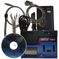
... Microchip Technology Inc. GENERAL SPECIFICATIONS Description 20.3W Dual Output +3.3VDC/5A, +5.0VDC/0.75A, w/ 5-pin Mini Din plug USB A-B M-M cable, 6 feet RS-232 DB9 (1 end male, 1 end female) ″ 18 15-pin, 22 AWG Super Flex Stranded Series 200 wire leads with keyed housing ...
Page 108
... DD PP ® POWER VIA MPLAB PM3 9-14V in 125 mV steps 150 mA max 2-5.5V in 125 mV steps 500 mA max Over Voltage Shutdown POWER VIA TARGET 2-5.5V 9-14V in 125 mV steps -150 mA max 2-5.5V I Overcurrent Fuse, Over Voltage Shutdown PP Value Value © 2006 Microchip Technology Inc. ...
Page 109
... TABLE A-8: Parameter The GO signal has internal 10K pull-up to +5.0V and a 0.1 μF cap to GND. Note: © 2006 Microchip Technology Inc. ICSP™ I/O OPERATING CHARACTERISTICS Conditions Supply Voltage Range Minimum High-level Input Voltage Maximum Low-level Input Voltage Minimum High-level Output Voltage @ I = -50 μ ...
Page 110
... Max CC 2.00 5.50 2.0 1.50 3.0 2.10 4.5 3.15 5.5 3.85 2.0 0.50 3.0 0.90 4.5 1.35 5.5 1.65 2.0 1.90 3.0 2.90 2.0 0.10 3.0 0.10 4.5 0. 3.0 -24 mA 4.5 - © 2006 Microchip Technology Inc. ...
Page 111
... All sockets (except Yamaichi) are labeled with the manufacturer’s name. Identify a Yamaichi socket by looking for the letters IC51– (as the prefix to a part number) on the socket. © 2006 Microchip Technology Inc. SOCKET MODULE ALIGNMENT CAUTION SOCKET LIFE EXPECTANCY AND CLEANING METHOD ...
Page 112
... DS51464C-page 106 DANGER TYPICAL PROGRAMMING TIMES IN STAND-ALONE MODE Device PIC12F675 PIC16F877A PIC16F819 PIC18F452 PIC16F88 PIC16C55A PIC17C44 PIC12C509 PIC16F77 PIC16F877 PIC18F8720 Programming Time 4 seconds 5 seconds 4 seconds 7 seconds 3.7 seconds 2.5 seconds 10 seconds 4 seconds 6.6 seconds 37 seconds 24 seconds © 2006 Microchip Technology Inc. ...
Page 113
... If you can program a master chip, and if you can read and try to program code-protected chips, but the chips fail the programming attempts, then potential socket pin damage may be the cause of the problem. Contact your Microchip Field Application Engineer (FAE) if your socket module is not operating properly. © 2006 Microchip Technology Inc. MPLAB PM3 ® ...
Page 114
... Make sure that the RS-232 cable is connected, the power supply is connected and the power switch on MPLAB PM3 is on. 4. Try connecting MPLAB PM3 to a different serial port. If your PC has a 25-pin serial port, you will need a 25-to-9 serial port adapter. DS51464C-page 108 © 2006 Microchip Technology Inc. ...
Page 115
... MPLAB PM3 Operating System, a message box will appear when you try to enable the programmer. Make sure you allow MPLAB PM3 to upgrade to get the latest versions for MPLAB IDE software and MPLAB PM3 operating system (Section 7.8 “Upgrading the MPLAB PM3 Operating System”). © 2006 Microchip Technology Inc. DS51464C-page 109 ...
Page 116
... This is where you can set flow control to Hardware. To turn off FIFO, click the Port Settings tab, and click the Advanced button. Deselect the Use FIFO box, and click OK. Reboot the PC to implement the change. DS51464C-page 110 © 2006 Microchip Technology Inc. ...
Page 117
... On Windows NT/2000/XP, select Settings>Control Panel from the Start menu. Select System and double click on Ports. Click on a COM port from the list and then click Settings. In the Settings dialog, click Advanced. Make sure there are no IRQ conflicts. © 2006 Microchip Technology Inc. CAUTION DS51464C-page 111 ...
Page 118
... MPLAB IDE. If the card is not supported, the MPLAB PM3 Card will not appear on the Programmer menu. (See the Readme for MPLAB PM3 for a list of recommended cards.) DS51464C-page 112 © 2006 Microchip Technology Inc. ...
Page 119
... If a device has been programmed with the parity Configuration bit set to “OFF,” the parity checking cannot be turned back to “ON.” A blank device will have to be used. © 2006 Microchip Technology Inc. DS51464C-page 113 ...
Page 120
... Display Read Write Test Failure Reset the unit. If the problem persists, contact your field representative to SAR the unit. FPGA Time-out Reset the unit. If the problem persists, contact your field representative to SAR the unit. Corrective Action © 2006 Microchip Technology Inc. ...
Page 121
... Display Read Write Failure 26 Power Monitor Can Not Ramp Up Voltages 27 Updating Failed © 2006 Microchip Technology Inc. BIOS ERROR CODES Definition Reset and connect to MPLAB Reset and connect to MPLAB IDE. Reset the unit. If the problem persists, contact your field representative to SAR the unit. ...
Page 122
... Your own memory read/write routines must be used for these ROMless devices. B.8.2.2 MPLAB PM3 LIMITATIONS FOR ALL DEVICES • For ICSP you must connect the AV V pins for the device to program. SS DS51464C-page 116 and AV pins in addition to the © 2006 Microchip Technology Inc. and DD ...
Page 123
... Assembly Language A programming language that describes binary machine code in a symbolic form. Asynchronous Stimulus Data generated to simulate external inputs to a simulator device. Breakpoint, Hardware An event whose execution will cause a halt. © 2006 Microchip Technology Inc. USER’S GUIDE Glossary MPLAB PM3 ® ...
Page 124
... A tool used to program electrically programmable semiconductor devices such as microcontrollers. Directives Statements in source code that provide control of the language tool’s operation. Download Download is the process of sending data from a host to another device, such as an emulator, programmer or target board. DS51464C-page 118 © 2006 Microchip Technology Inc. ...
Page 125
... A process performed by the linker in which external symbol definitions from all input modules are collected in an attempt to resolve all external symbol references. Any external symbol references which do not have a corresponding definition cause a linker error to be reported. © 2006 Microchip Technology Inc. DS51464C-page 119 ...
Page 126
... Integrated Development Environment. MPLAB IDE is Microchip’s integrated development environment. Import Bring data into MPLAB IDE from an outside source, such as from a HEX file. Instruction Set The collection of machine language instructions that a particular processor understands. DS51464C-page 120 © 2006 Microchip Technology Inc. ...
Page 127
... Listing File A listing file is an ASCII text file that shows the machine code generated for each C source statement, assembly instruction, assembler directive, or macro encountered in a source file. © 2006 Microchip Technology Inc. DS51464C-page 121 ...
Page 128
... One of the possible program memory configurations of the PIC17CXXX and PIC18CXXX families of microcontrollers. In microprocessor mode, the on-chip program memory is not used. The entire program memory is mapped externally. Mnemonics Text instructions that can be translated directly into machine code. Also referred to as Opcodes. DS51464C-page 122 © 2006 Microchip Technology Inc. ...
Page 129
... MPLINK linker is an object linker for the Microchip MPASM assembler and the Microchip MPLAB C17 or C18 C compilers. MPLINK linker also may be used with the Microchip MPLIB librarian. MPLINK linker is designed to be used with MPLAB IDE, though it does not have to be. © 2006 Microchip Technology Inc. DS51464C-page 123 ...
Page 130
... When the pass count value reaches zero, the event is satisfied. You can assign the Pass Counter to break and trace logic, and to any sequential event in the complex trigger dialog. PC Personal Computer or Program Counter. DS51464C-page 124 © 2006 Microchip Technology Inc. ...
Page 131
... Radix The number base, HEX, or decimal, used in specifying an address. RAM Random Access Memory (Data Memory). Memory in which information can be accessed in any order. Raw Data The binary representation of code or data associated with a section. © 2006 Microchip Technology Inc. DS51464C-page 125 ...
Page 132
... The trace buffer captures the information that is on the bus at one instance. Therefore, one trace buffer entry will contain execution information for three instructions. The number of captured cycles from one piece of information to another for a single instruction execution is referred to as the skew. DS51464C-page 126 © 2006 Microchip Technology Inc. ...
Page 133
... Input to the simulator, i.e., data generated to exercise the response of simulation to external signals. Often the data is put into the form of a list of actions in a text file. Stimulus may be asynchronous, synchronous (pin), clocked and register. Stopwatch A counter for measuring execution cycles. © 2006 Microchip Technology Inc. DS51464C-page 127 ...
Page 134
... The Upload function transfers data from a tool, such as an emulator or programmer, to the host PC or from the target board to the emulator. Warning An alert that is provided to warn you of a situation that would cause physical damage to a device, software file, or equipment. DS51464C-page 128 © 2006 Microchip Technology Inc. ...
Page 135
... Watch windows contain a list of watch variables that are updated at each breakpoint. Watchdog Timer A timer on a PICmicro microcontroller that resets the processor after a selectable length of time. The WDT is enabled or disabled and set up using Configuration bits. WDT See Watchdog Timer. © 2006 Microchip Technology Inc. DS51464C-page 129 ...
Page 136
... NOTES: DS51464C-page 130 © 2006 Microchip Technology Inc. ...
Page 137
... ICSP Cable Installation ............................................ 15 ICSP Hardware Specifications ............................... 101 Indicators Lights and Buzzer ............................................. 16 Installation Hardware .......................................................... 12 ICSP Cable ....................................................... 15 MPLAB PM3 ..................................................... 11 Software............................................................ 11 USB Driver ........................................................ 12 Internet Address......................................................... 5 © 2006 Microchip Technology Inc. Index K Keys ......................................................................... 77 L LCD .......................................................................... 77 Loading an Environment .......................................... 52 M Memory Ranges....................................................... 62 Microchip Internet Web Site ....................................... 5 MPASM Assembler .................................................. 10 MPLAB CXX ...
Page 138
... Software Installation ................................................. 11 SQTP ................................................................... 7 Stand-Alone Mode ............................................... 9 Starting MPLAB IDE................................................. 16 Starting MPLAB PM3 ............................................... 20 T Transfer from MPLAB PM3 ...................................... 61 Transfer to MPLAB PM3 .......................................... 61 Troubleshooting ..................................................... 107 U USB Driver Installation ............................................. 12 V Verify ........................................................................ 59 Voltages ................................................................... 63 W Warranty Registration................................................. 4 Windowed Device..................................................... 41 WWW Address ........................................................... 5 DS51464C-page 132 © 2006 Microchip Technology Inc. ...
Page 139
... NOTES: © 2006 Microchip Technology Inc. DS51464C-page 133 ...
Page 140
... Fax: 886-3-572-6459 Taiwan - Kaohsiung Tel: 886-7-536-4818 Fax: 886-7-536-4803 Taiwan - Taipei Tel: 886-2-2500-6610 Fax: 886-2-2508-0102 Thailand - Bangkok Tel: 66-2-694-1351 Fax: 66-2-694-1350 © 2006 Microchip Technology Inc. EUROPE Austria - Wels Tel: 43-7242-2244-399 Fax: 43-7242-2244-393 Denmark - Copenhagen Tel: 45-4450-2828 Fax: 45-4485-2829 France - Paris Tel: 33-1-69-53-63-20 ...