DV007004 Microchip Technology, DV007004 Datasheet - Page 65
DV007004
Manufacturer Part Number
DV007004
Description
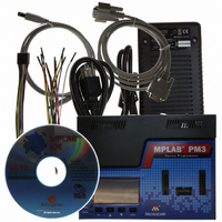
PROGRAMMER UNIVERSAL PM3
Manufacturer
Microchip Technology
Series
MPLAB® PM3r
Type
Universalr
Specifications of DV007004
Contents
MPLAB PM3 Programming Unit, Cables, Power Supply and IDE
Positions/sockets
1
Ic Product Type
Programmer, Universal
Supported Families
PICmicro, DsPIC30F
Kit Contents
LCD, ICSP Support, 40-pin Socket, Digital/Multimedia Card Slot
Rohs Compliant
NA
Lead Free Status / RoHS Status
Lead free / RoHS Compliant
For Use With/related Products
Microchip's PICmicro devices including dsPIC30F
Lead Free Status / Rohs Status
Lead free / RoHS Compliant
For Use With
PICmicro And DsPIC30F DSC Devices
Lead Free Status / RoHS Status
Lead free / RoHS Compliant, Lead free / RoHS Compliant
Available stocks
Company
Part Number
Manufacturer
Quantity
Price
Company:

Part Number:
DV007004
Manufacturer:
Microchip Technology
Quantity:
135
Company:
Part Number:
DV007004
Manufacturer:
MICROCHIP
Quantity:
12 000
Company:
Part Number:
DV007004 (MPLAB PM3)
Manufacturer:
MICROCHIP
Quantity:
12 000


© 2006 Microchip Technology Inc.
You can view the Program Memory as hex code, machine code or disassembled with
symbols (if available). Change the display mode by clicking on the Display Option
button in the lower left corner of the window.
When the MPLAB ICE emulator is selected as the Debugger, the Program Memory
window shows the data that is in the emulation memory of the MPLAB ICE pod. This
memory is read by the MPLAB ICE probe when run, single stepped or traced using the
emulator.
When the simulator is selected as the Debugger, the Program Memory window reflects
the contents of a memory buffer on the PC. This memory is read by MPLAB SIM when
run, single stepped or traced.
If program memory is read with the MPLAB PM3 programmer while in emulator or
simulator mode, it will overwrite the program memory being emulated or simulated.
This can cause “mismatches” between the program memory and debug information if
an MPLAB IDE project is open. The system displays an option to either close the cur-
rent MPLAB IDE project or to continue and read the device’s memory into the Program
Memory window. Subsequent debug operations might not work properly.
7.4.3
To disable the MPLAB PM3 programmer, select Programmer>Disable Programmer.
7.4.4
Select Programmer>Program to program the entire device (i.e., all of the program
memory, Configuration bits, etc.).
To program selectively (e.g., part of program memory, only Configuration bits), select
Programmer>Settings to open the Programmer Settings dialog. Click the Memory
Ranges tab and select the options for programming. Areas that are grayed out are not
available on the device. Click OK. Then select Programmer>Program to program the
device. The memory area corresponding to the checked boxes will be programmed.
After MPLAB PM3 programs a device, it automatically performs a verify operation and
displays any errors found. An additional verify operation may be done via selecting
Programmer>Verify.
7.4.5
To verify the programming on the device, select Programmer>Verify. This verifies that
the programming on the device matches the program memory, Configuration bits, ID
locations, EEPROM and calibration memory values in MPLAB IDE and in the Settings
dialog and Configuration Bits dialog.
If there are more errors than expected and those errors claim that the bad data is all
zeros (0000), the socket module might not be seated properly. Remove and reseat the
socket module. It is always a good practice to insert a known blank device and do a
Blank Check whenever the socket module is changed.
When the programming is finished, “Programming/Verification completed
successfully!” will be displayed in the Output window. If the programming failed,
an error message will appear showing the good (expected) data and the bad (actual)
data for each address it attempted to program.
Disable Programmer
Program
Verify
DS51464C-page 59
Related parts for DV007004
Image
Part Number
Description
Manufacturer
Datasheet
Request
R

Part Number:
Description:
Manufacturer:
Microchip Technology Inc.
Datasheet:
Part Number:
Description:
Manufacturer:
Microchip Technology Inc.
Datasheet:
Part Number:
Description:
Manufacturer:
Microchip Technology Inc.
Datasheet:
Part Number:
Description:
Manufacturer:
Microchip Technology Inc.
Datasheet:
Part Number:
Description:
Manufacturer:
Microchip Technology Inc.
Datasheet:
Part Number:
Description:
Manufacturer:
Microchip Technology Inc.
Datasheet:
Part Number:
Description:
Manufacturer:
Microchip Technology Inc.
Datasheet:
Part Number:
Description:
Manufacturer:
Microchip Technology Inc.
Datasheet: