MC68HC908JB8JPE Freescale Semiconductor, MC68HC908JB8JPE Datasheet - Page 130
MC68HC908JB8JPE
Manufacturer Part Number
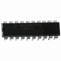
MC68HC908JB8JPE
Description
IC MCU FLASH 8BIT 8K 20-DIP
Manufacturer
Freescale Semiconductor
Series
HC08r
Datasheet
1.MC908JB8JDWE.pdf
(286 pages)
Specifications of MC68HC908JB8JPE
Core Processor
HC08
Core Size
8-Bit
Speed
3MHz
Connectivity
USB
Peripherals
LVD, POR, PWM
Number Of I /o
13
Program Memory Size
8KB (8K x 8)
Program Memory Type
FLASH
Ram Size
256 x 8
Voltage - Supply (vcc/vdd)
4 V ~ 5.5 V
Oscillator Type
Internal
Operating Temperature
0°C ~ 70°C
Package / Case
20-DIP (0.300", 7.62mm)
Controller Family/series
HC08
No. Of I/o's
13
Ram Memory Size
256Byte
Cpu Speed
3MHz
No. Of Timers
1
Embedded Interface Type
USB
Rohs Compliant
Yes
Processor Series
HC08JB
Core
HC08
Data Bus Width
8 bit
Data Ram Size
256 B
Interface Type
USB
Maximum Clock Frequency
3 MHz
Number Of Programmable I/os
37
Number Of Timers
2
Operating Supply Voltage
4 V to 5.5 V
Maximum Operating Temperature
+ 70 C
Mounting Style
Through Hole
Development Tools By Supplier
FSICEBASE, DEMO908GZ60E, M68EML08GZE, KITUSBSPIDGLEVME, KITUSBSPIEVME, KIT33810EKEVME
Minimum Operating Temperature
0 C
Lead Free Status / RoHS Status
Lead free / RoHS Compliant
Eeprom Size
-
Data Converters
-
Lead Free Status / Rohs Status
Details


Universal Serial Bus Module (USB)
9.5.3 Suspend
Technical Data
130
NOTE:
The reset flag bit (RSTF) in the USB interrupt register 1 (UIR1) also will
be set after the internal reset is removed. Refer to
Register 1
After a reset is removed, the device will be in the default, but not yet
addressed or configured state (refer to Section 9.1 USB Device States
of the Universal Serial Bus Specification Rev. 1.1). The device must be
able to accept a device address via a SET_ADDRESS command (refer
to Section 9.4 Standard Device Request in the Universal Serial Bus
Specification Rev. 1.1) no later than 10 ms after the reset is removed.
Reset can wake a device from the suspended mode.
USB Reset can be configured not to generate a reset signal to the CPU
by setting the URSTD bit of the configuration register (see
Configuration Register
CPU generates an USB interrupt.
The MCU supports suspend mode for low power. Suspend mode should
be entered when the USB data lines are in the idle state for more than
3ms. Entry into suspend mode is controlled by the SUSPND bit in the
USB interrupt register. Any low-speed bus activity should keep the
device out of the suspend state. Low-speed devices are kept awake by
periodic low-speed EOP signals from the host. This is referred to as low
speed keep alive (refer to Section 11.8.4.1 Low-Speed Keep-alive in the
Universal Serial Bus Specification Rev. 1.1).
Firmware should monitor the EOPF flag and enter suspend mode by
setting the SUSPND bit if an EOP is not detected for 3ms.
Per the USB specification, the bus powered USB system is required to
draw less than 500µA from the V
This includes the current supplied by the voltage regulator to the 1.5kΩ
to ground termination resistors placed at the host end of the USB bus.
This low-current requirement means that firmware is responsible for
entering stop mode once the USB module has been placed in the
suspend state.
Universal Serial Bus Module (USB)
for more detail.
MC68HC908JB8•MC68HC08JB8•MC68HC08JT8 — Rev. 2.3
(CONFIG)). When a USB reset is detected, the
DD
supply when in the suspend state.
Freescale Semiconductor
9.8.3 USB Interrupt
Section 5.
Related parts for MC68HC908JB8JPE
Image
Part Number
Description
Manufacturer
Datasheet
Request
R

Part Number:
Description:
Manufacturer:
Freescale Semiconductor, Inc
Datasheet:
Part Number:
Description:
Manufacturer:
Freescale Semiconductor, Inc
Datasheet:
Part Number:
Description:
Manufacturer:
Freescale Semiconductor, Inc
Datasheet:
Part Number:
Description:
Manufacturer:
Freescale Semiconductor, Inc
Datasheet:
Part Number:
Description:
Manufacturer:
Freescale Semiconductor, Inc
Datasheet:
Part Number:
Description:
Manufacturer:
Freescale Semiconductor, Inc
Datasheet:
Part Number:
Description:
Manufacturer:
Freescale Semiconductor, Inc
Datasheet:
Part Number:
Description:
Manufacturer:
Freescale Semiconductor, Inc
Datasheet:
Part Number:
Description:
Manufacturer:
Freescale Semiconductor, Inc
Datasheet:
Part Number:
Description:
Manufacturer:
Freescale Semiconductor, Inc
Datasheet:
Part Number:
Description:
Manufacturer:
Freescale Semiconductor, Inc
Datasheet:
Part Number:
Description:
Manufacturer:
Freescale Semiconductor, Inc
Datasheet:
Part Number:
Description:
Manufacturer:
Freescale Semiconductor, Inc
Datasheet:
Part Number:
Description:
Manufacturer:
Freescale Semiconductor, Inc
Datasheet:
Part Number:
Description:
Manufacturer:
Freescale Semiconductor, Inc
Datasheet: