MC68HC908JB8JPE Freescale Semiconductor, MC68HC908JB8JPE Datasheet - Page 259
MC68HC908JB8JPE
Manufacturer Part Number
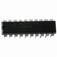
MC68HC908JB8JPE
Description
IC MCU FLASH 8BIT 8K 20-DIP
Manufacturer
Freescale Semiconductor
Series
HC08r
Datasheet
1.MC908JB8JDWE.pdf
(286 pages)
Specifications of MC68HC908JB8JPE
Core Processor
HC08
Core Size
8-Bit
Speed
3MHz
Connectivity
USB
Peripherals
LVD, POR, PWM
Number Of I /o
13
Program Memory Size
8KB (8K x 8)
Program Memory Type
FLASH
Ram Size
256 x 8
Voltage - Supply (vcc/vdd)
4 V ~ 5.5 V
Oscillator Type
Internal
Operating Temperature
0°C ~ 70°C
Package / Case
20-DIP (0.300", 7.62mm)
Controller Family/series
HC08
No. Of I/o's
13
Ram Memory Size
256Byte
Cpu Speed
3MHz
No. Of Timers
1
Embedded Interface Type
USB
Rohs Compliant
Yes
Processor Series
HC08JB
Core
HC08
Data Bus Width
8 bit
Data Ram Size
256 B
Interface Type
USB
Maximum Clock Frequency
3 MHz
Number Of Programmable I/os
37
Number Of Timers
2
Operating Supply Voltage
4 V to 5.5 V
Maximum Operating Temperature
+ 70 C
Mounting Style
Through Hole
Development Tools By Supplier
FSICEBASE, DEMO908GZ60E, M68EML08GZE, KITUSBSPIDGLEVME, KITUSBSPIEVME, KIT33810EKEVME
Minimum Operating Temperature
0 C
Lead Free Status / RoHS Status
Lead free / RoHS Compliant
Eeprom Size
-
Data Converters
-
Lead Free Status / Rohs Status
Details


18.10 USB Low-Speed Source Electrical Characteristics
MC68HC908JB8•MC68HC08JB8•MC68HC08JT8 — Rev. 2.3
Freescale Semiconductor
NOTES:
Internal operating frequency
Transition time
Rise time
Fall time
Rise/Fall time matching
Low speed data rate
Source differential driver jitter
To next transition
For paired transitions
Receiver data jitter tolerance
To next transition
For paired transitions
Source SEO interval of EOP
Source jitter for differential transition
to SE0 transition
Receiver SEO interval of EOP
Must reject as EOP
Must accept
Width of SEO interval during
differential transition
1. All voltages are measured from local ground, unless otherwise specified. All timings use a capacitive load of 50 pF, unless
2. Transition times are measured from 10% to 90% of the data signal. The rising and falling edges should be smoothly tran-
3. The two transitions are a (nominal) bit time apart.
otherwise specified. Low-speed timings have a 1.5kΩ pullup to 2.8 V on the D– data line.
sitioning (monotonic). Capacitive loading includes 50 pF of tester capacitance.
Characteristic
(2)
(3)
(1)
Symbol
t
t
t
t
LEOPR1
LEOPR2
DRATE
LEOPT
t
t
t
t
t
t
DDJ1
DDJ2
DJR1
DJR2
f
RFM
LST
Electrical Specifications
OP
t
t
R
F
1.5 Mbs ± 1.5%
crossover point
crossover point
crossover point
crossover point
crossover point
crossover point
Measured at
Measured at
Measured at
Measured at
Measured at
Measured at
C
C
C
C
Conditions
C
C
L
L
L
L
L
L
= 200 pF
= 200 pF
= 600 pF
= 600 pF
= 600pF
= 600pF
t
R
—
/t
USB Low-Speed Source Electrical Characteristics
F
1.4775
676.8
1.25
Min
–25
–10
–75
–45
210
670
75
75
80
—
—
1.500
666.0
Typ
667
—
—
—
—
—
—
—
—
—
—
—
3
Electrical Specifications
1.5225
656.8
Max
1.50
300
300
120
210
25
10
75
45
—
—
—
Technical Data
MHz
Unit
Mbs
µs
ns
ns
ns
ns
ns
ns
ns
%
259
Related parts for MC68HC908JB8JPE
Image
Part Number
Description
Manufacturer
Datasheet
Request
R

Part Number:
Description:
Manufacturer:
Freescale Semiconductor, Inc
Datasheet:
Part Number:
Description:
Manufacturer:
Freescale Semiconductor, Inc
Datasheet:
Part Number:
Description:
Manufacturer:
Freescale Semiconductor, Inc
Datasheet:
Part Number:
Description:
Manufacturer:
Freescale Semiconductor, Inc
Datasheet:
Part Number:
Description:
Manufacturer:
Freescale Semiconductor, Inc
Datasheet:
Part Number:
Description:
Manufacturer:
Freescale Semiconductor, Inc
Datasheet:
Part Number:
Description:
Manufacturer:
Freescale Semiconductor, Inc
Datasheet:
Part Number:
Description:
Manufacturer:
Freescale Semiconductor, Inc
Datasheet:
Part Number:
Description:
Manufacturer:
Freescale Semiconductor, Inc
Datasheet:
Part Number:
Description:
Manufacturer:
Freescale Semiconductor, Inc
Datasheet:
Part Number:
Description:
Manufacturer:
Freescale Semiconductor, Inc
Datasheet:
Part Number:
Description:
Manufacturer:
Freescale Semiconductor, Inc
Datasheet:
Part Number:
Description:
Manufacturer:
Freescale Semiconductor, Inc
Datasheet:
Part Number:
Description:
Manufacturer:
Freescale Semiconductor, Inc
Datasheet:
Part Number:
Description:
Manufacturer:
Freescale Semiconductor, Inc
Datasheet: