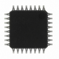
M37544G2AGP#U0 Renesas Electronics America, M37544G2AGP#U0 Datasheet - Page 42

M37544G2AGP#U0
Manufacturer Part Number
M37544G2AGP#U0
Description
IC 740 MCU OTP 8K 32LQFP
Manufacturer
Renesas Electronics America
Series
740/38000r
Specifications of M37544G2AGP#U0
Core Processor
740
Core Size
8-Bit
Speed
8MHz
Connectivity
SIO, UART/USART
Peripherals
WDT
Number Of I /o
25
Program Memory Size
8KB (8K x 8)
Program Memory Type
QzROM
Ram Size
256 x 8
Voltage - Supply (vcc/vdd)
4 V ~ 5.5 V
Data Converters
A/D 6x8b
Oscillator Type
Internal
Operating Temperature
-20°C ~ 85°C
Package / Case
32-LQFP
Lead Free Status / RoHS Status
Lead free / RoHS Compliant
Eeprom Size
-
Available stocks
Company
Part Number
Manufacturer
Quantity
Price
REJ03B0108-0103
page 40 of 72
7544 Group (QzROM version)
Clock Generating Circuit
An oscillation circuit can be formed by connecting a resonator be-
tween X
by connecting a resistor and a capacitor.
Use the circuit constants in accordance with the resonator
manufacturer's recommended values.
No external resistor is needed between X
feed-back resistor exists on-chip. (An external feed-back resistor
may be needed depending on conditions.)
(1) On-chip oscillator operation
When the MCU operates by the on-chip oscillator for the main
clock, connect X
The clock frequency of the on-chip oscillator depends on the sup-
ply voltage and the operation temperature range.
Be careful that variable frequencies when designing application
products.
(2) Ceramic resonator and quartz-crystal oscillator
When the ceramic resonator and quartz-crystal oscillator is used
for the main clock, connect the ceramic/quartz-crystal oscillator
and the external circuit to pins X
tance. A feedback resistor is built in between pins X
(3) RC oscillation
When the RC oscillation is used for the main clock, connect the
X
capacitor C at the shortest distance.
The frequency is affected by a capacitor, a resistor and a micro-
computer.
So, set the constants within the range of the frequency limits.
(4) External clock
When the external signal clock is used for the main clock, connect
the X
IN
pin and X
IN
pin to the clock source and leave X
IN
and X
OUT
IN
OUT
pin to the external circuit of resistor R and the
pin to V
, and an RC oscillation circuit can be formed
Rev.1.03
CC
and leave X
IN
and X
Mar 31, 2009
OUT
OUT
OUT
IN
pin open.
at the shortest dis-
and X
pin open.
IN
OUT
and X
since a
OUT
.
Fig. 41 Processing of X
Fig. 42 External circuit of ceramic resonator and quartz-crystal
Fig. 43 External circuit of RC oscillation
Fig. 44 External clock input circuit
Note:
X
IN
X
Insert a damping resistor if required.
The resistance will vary depending on the oscillator and
the oscillation drive capacity setting.
Use the value recommended by the maker of the oscillator.
Also, if the oscillator manufacturer’s data sheet specifies
that a feedback resistor be added external to the chip
through a feedback resistor exists on-chip, insert a feed-
back resistor between X
instruction.
oscillator
IN
External oscillation
circuit
M37544
M37544
X
V
V
IN
CC
SS
X
IN
IN
C
IN
and X
Open
X
X
OUT
OUT
M37544
OUT
M37544
Note:
pins at on-chip oscillator operation
IN
Note:
The clock frequency of the
on-chip oscillator depends
on the supply voltage and
the operation temperature
range.
Be careful that variable fre-
quencies and obtain the
sufficient margin.
and X
R
C
X
OUT
Connect the external
circuit of resistor R
and the capacitor C at
the shortest distance.
The frequency is af-
fected by a capacitor,
a resistor and a micro-
computer.
So, set the constants
within the range of the
frequency limits.
Rd (Note)
C
OUT
Open
X
OUT
OUT
following the


