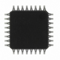
M37544G2AGP#U0 Renesas Electronics America, M37544G2AGP#U0 Datasheet - Page 46

M37544G2AGP#U0
Manufacturer Part Number
M37544G2AGP#U0
Description
IC 740 MCU OTP 8K 32LQFP
Manufacturer
Renesas Electronics America
Series
740/38000r
Specifications of M37544G2AGP#U0
Core Processor
740
Core Size
8-Bit
Speed
8MHz
Connectivity
SIO, UART/USART
Peripherals
WDT
Number Of I /o
25
Program Memory Size
8KB (8K x 8)
Program Memory Type
QzROM
Ram Size
256 x 8
Voltage - Supply (vcc/vdd)
4 V ~ 5.5 V
Data Converters
A/D 6x8b
Oscillator Type
Internal
Operating Temperature
-20°C ~ 85°C
Package / Case
32-LQFP
Lead Free Status / RoHS Status
Lead free / RoHS Compliant
Eeprom Size
-
Available stocks
Company
Part Number
Manufacturer
Quantity
Price
REJ03B0108-0103
page 44 of 72
7544 Group (QzROM version)
Fig. 49 State transition
Operation clock source:
f(X
f(X
On-chip oscillator stop
IN
IN
) (Note 1)
) oscillation enabled
State 1
Oscillation stop detection circuit valid
Rev.1.03
Operation clock source:
f(X
f(X
On-chip oscillator enabled
CPUM
CPUM
Interrupt
STP
instruction
IN
IN
) (Note 1)
) oscillation enabled
3
MISRG
3
¨1
←0
2
State 2’
2
Operation clock source:
f(X
f(X
On-chip oscillator enabled
1
¨1
Mar 31, 2009
2
IN
IN
Interrupt
) (Note 1)
) oscillation enabled
Stop mode
State 2
MISRG
WIT
instruction
CPUM
CPUM
1
←0
(Note 2)
76
76
2
¨10
←00
01
11
2
2
2
2
Operation clock source:
On-chip oscillator (Note 3)
f(X
On-chip oscillator enabled
CPUM
IN
CPUM
MISRG
) oscillation enabled
76
(Note 2)
¨10
76
¨00
State 3’
2
01
11
1
¨1
Reset released
2
2
2
2
Operation clock source:
On-chip oscillator (Note 3)
f(X
On-chip oscillator enabled
IN
Wait mode
) oscillation enabled
MISRG
State 3
Reset state
1
¨0
2
Interrupt
CPUM
CPUM
Notes on switch of clock
(1) In operation clock source = f(X
selected for the CPU clock division ratio.
(2) Execute the state transition state 3 to state 2 or
state 3’ to state 2’ after stabilizing X
(3) In operation clock source = on-chip oscillator, the middle-
speed mode is selected for the CPU clock division ratio.
(4) When the state transition state 2 → state 3 → state 4
is performed, execute the NOP instruction as shown below
according to the division ratio of CPU clock.
• CPUM76 → 10
• NOP instruction
• CPUM4 → 1
Double-speed mode at on-chip oscillator: NOP
High-speed mode at on-chip oscillator: NOP
Middle-speed mode at on-chip oscillator: NOP
4
4
←1
¨0
oscillation)
f(X
f(X
f(X
2
WIT
instruction
2
IN
IN
IN
)/2 (high-speed mode)
)/8 (middle-speed mode)
) (double-speed mode, only at a ceramic/quartz-crystal
Operation clock source:
On-chip oscillator (Note 3)
f(X
On-chip oscillator enabled
IN
) oscillation stop
2
(State 3 → state 4)
2
State 4
(State 2 → state 3)
IN
IN
), the following can be
oscillation.
1
0
3


