M37544G2AGP#U0 Renesas Electronics America, M37544G2AGP#U0 Datasheet - Page 72
M37544G2AGP#U0
Manufacturer Part Number
M37544G2AGP#U0
Description
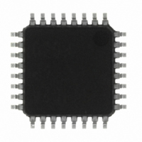
IC 740 MCU OTP 8K 32LQFP
Manufacturer
Renesas Electronics America
Series
740/38000r
Specifications of M37544G2AGP#U0
Core Processor
740
Core Size
8-Bit
Speed
8MHz
Connectivity
SIO, UART/USART
Peripherals
WDT
Number Of I /o
25
Program Memory Size
8KB (8K x 8)
Program Memory Type
QzROM
Ram Size
256 x 8
Voltage - Supply (vcc/vdd)
4 V ~ 5.5 V
Data Converters
A/D 6x8b
Oscillator Type
Internal
Operating Temperature
-20°C ~ 85°C
Package / Case
32-LQFP
Lead Free Status / RoHS Status
Lead free / RoHS Compliant
Eeprom Size
-
Available stocks
Company
Part Number
Manufacturer
Quantity
Price


REJ03B0108-0103
page 70 of 72
7544 Group (QzROM version)
4. I/O pin function when serial I/O is enabled.
The pin functions of P1
follows according to the setting values of a serial I/O mode selec-
tion bit (bit 6 of serial I/O control register (address 001A
serial I/O synchronous clock selection bit (bit 1 of serial I/O control
register).
(1) Serial I/O mode selection bit → “1” :
Clock synchronous type serial I/O is selected.
• Setup of a serial I/O synchronous clock selection bit
“0” : P1
“1” : P1
• Setup of a S
“0” : P1
“1” : P1
(2) Serial I/O mode selection bit → “0” :
Clock asynchronous (UART) type serial I/O is selected.
• Setup of a serial I/O synchronous clock selection bit
“0”: P1
“1”: P1
• When clock asynchronous (UART) type serial I/O is selected, it
Notes on A/D conversion
1. Analog input pin
Make the signal source impedance for analog input low, or equip
an analog input pin with an external capacitor of 0.01µF to 1µF.
Further, be sure to verify the operation of application products on
the user side.
<Reason>
An analog input pin includes the capacitor for analog voltage com-
parison. Accordingly, when signals from signal source with high
impedance are input to an analog input pin, charge and discharge
noise generates. This may cause the A/D conversion/comparison
precision to be worse.
2. Clock frequency during A/D conversion
The comparator consists of a capacity coupling, and a charge of
the capacity will be lost if the clock frequency is too low. This may
cause the A/D conversion precision to be worse. Accordingly, set
f(X
during A/D conversion.
functions P1
IN
) in order that the A/D conversion clock is 500 kHz or over
2
2
2
2
3
3
pin can be used as a normal I/O pin.
pin turns into an input pin of an external clock.
pin turns into an output pin of a synchronous clock.
pin turns into an input pin of a synchronous clock.
pin can be used as a normal I/O pin.
pin turns into a S
RDY
3
pin. It can be used as a normal I/O pin.
output enable bit (SRDY)
Rev.1.03
2
/S
RDY
CLK
output pin.
and P1
Mar 31, 2009
3
/S
RDY
are switched to as
16
)) and a
3. A/D conversion accuracy
As for AD translation accuracy, on the following operating condi-
tions, accuracy may become low.
(1) Since the analog circuit inside a microcomputer becomes sen-
(2) When V
Notes on Watchdog Timer
1. The watchdog timer is operating during the wait mode. Write
2. The watchdog timer stops during the stop mode. However, the
3. The STP instruction function selection bit (bit 6 of watchdog
Notes on RESET pin
1. Connecting capacitor
In case where the RESET signal rise time is long, connect a ce-
ramic capacitor or others across the RESET pin and the Vss pin.
And use a 1000 pF or more capacitor for high frequency use.
When connecting the capacitor, note the following :
• Make the length of the wiring which is connected to a capacitor
• Be sure to verify the operation of application products on the
<Reason>
If the several nanosecond or several ten nanosecond impulse
noise enters the RESET pin, it may cause a microcomputer fail-
ure.
as short as possible.
user side.
data to the watchdog timer control register to prevent timer un-
derflow.
watchdog timer is running during the oscillation stabilizing time
after the STP instruction is released. In order to avoid the un-
derflow of the watchdog timer, the watchdog timer count source
selection bit (bit 7 of watchdog timer control register (address
0039
timer control register (address 0039
once after releasing reset. After rewriting it is disable to write
any data to this bit.
sitive to noise when V
voltage, accuracy may become low rather than the case
where V
value.
low temperature may become extremely low compared with
that at room temperature. When the system would be used at
low temperature, the use at V
mended.
16
)) before executing the STP instruction.
REF
REF
voltage is lower than [ 3.0 V ], the accuracy at the
voltage and Vcc voltage are set up to the same
REF
voltage is set up lower than Vcc
REF
=3.0 V or more is recom-
16
)) can be rewritten only
Related parts for M37544G2AGP#U0
Image
Part Number
Description
Manufacturer
Datasheet
Request
R

Part Number:
Description:
SINGLE-CHIP 8-BIT CMOS MICROCOMPUTER
Manufacturer:
RENESAS [Renesas Technology Corp]
Datasheet:

Part Number:
Description:
M37544 EMULATOR KIT (EK) FOR PC4
Manufacturer:
Renesas Electronics America

Part Number:
Description:
KIT STARTER FOR M16C/29
Manufacturer:
Renesas Electronics America
Datasheet:

Part Number:
Description:
KIT STARTER FOR R8C/2D
Manufacturer:
Renesas Electronics America
Datasheet:

Part Number:
Description:
R0K33062P STARTER KIT
Manufacturer:
Renesas Electronics America
Datasheet:

Part Number:
Description:
KIT STARTER FOR R8C/23 E8A
Manufacturer:
Renesas Electronics America
Datasheet:

Part Number:
Description:
KIT STARTER FOR R8C/25
Manufacturer:
Renesas Electronics America
Datasheet:
Part Number:
Description:
KIT STARTER H8S2456 SHARPE DSPLY
Manufacturer:
Renesas Electronics America
Datasheet:

Part Number:
Description:
KIT STARTER FOR R8C38C
Manufacturer:
Renesas Electronics America
Datasheet:

Part Number:
Description:
KIT STARTER FOR R8C35C
Manufacturer:
Renesas Electronics America
Datasheet:

Part Number:
Description:
KIT STARTER FOR R8CL3AC+LCD APPS
Manufacturer:
Renesas Electronics America
Datasheet:
Part Number:
Description:
KIT STARTER FOR RX610
Manufacturer:
Renesas Electronics America
Datasheet:

Part Number:
Description:
KIT STARTER FOR R32C/118
Manufacturer:
Renesas Electronics America
Datasheet:

Part Number:
Description:
KIT DEV RSK-R8C/26-29
Manufacturer:
Renesas Electronics America
Datasheet:

Part Number:
Description:
KIT STARTER FOR SH7124
Manufacturer:
Renesas Electronics America
Datasheet: