M37544G2AGP#U0 Renesas Electronics America, M37544G2AGP#U0 Datasheet - Page 68
M37544G2AGP#U0
Manufacturer Part Number
M37544G2AGP#U0
Description
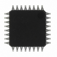
IC 740 MCU OTP 8K 32LQFP
Manufacturer
Renesas Electronics America
Series
740/38000r
Specifications of M37544G2AGP#U0
Core Processor
740
Core Size
8-Bit
Speed
8MHz
Connectivity
SIO, UART/USART
Peripherals
WDT
Number Of I /o
25
Program Memory Size
8KB (8K x 8)
Program Memory Type
QzROM
Ram Size
256 x 8
Voltage - Supply (vcc/vdd)
4 V ~ 5.5 V
Data Converters
A/D 6x8b
Oscillator Type
Internal
Operating Temperature
-20°C ~ 85°C
Package / Case
32-LQFP
Lead Free Status / RoHS Status
Lead free / RoHS Compliant
Eeprom Size
-
Available stocks
Company
Part Number
Manufacturer
Quantity
Price


REJ03B0108-0103
page 66 of 72
7544 Group (QzROM version)
6. Read-modify-write instruction
Do not execute a read-modify-write instruction to the read invalid
address (SFR).
The read-modify-write instruction operates in the following se-
quence: read one-byte of data from memory, modify the data,
write the data back to original memory. The following instructions
are classified as the read-modify-write instructions in the 740
Family.
(1) Bit management instructions: CLB, SEB
(2) Shift and rotate instructions: ASL, LSR, ROL, ROR, RRF
(3) Add and subtract instructions: DEC, INC
(4) Logical operation instructions (1’s complement): COM
Add and subtract/logical operation instructions (ADC, SBC, AND,
EOR, and ORA) when T flag = “1” operate in the way as the read-
modify-write instruction. Do not execute the read invalid SFR.
<Reason>
When the read-modify-write instruction is executed to read invalid
SFR, the instruction may cause the following consequence: the in-
struction reads unspecified data from the area due to the read
invalid condition. Then the instruction modifies this unspecified
data and writes the data to the area. The result will be random
data written to the area or some unexpected event.
NOTES ON PERIPHERAL FUNCTIONS
Notes on I/O Ports
1. Pull-up control register
When using each port which built in pull-up resistor as an output
port, the pull-up control bit of corresponding port becomes invalid,
and pull-up resistor is not connected.
<Reason>
Pull-up control is effective only when each direction register is set
to the input mode.
2. Notes in stand-by state
In stand-by state*
levels of an input port and an I/O port “undefined”.
Pull-up (connect the port to Vcc) or pull-down (connect the port to
Vss) these ports through a resistor.
When determining a resistance value, note the following points:
• External circuit
• Variation of output levels during the ordinary operation
• When setting as an input port : Fix its input level
• When setting as an output port : Prevent current from flowing out
<Reason>
The output transistor becomes the OFF state, which causes the
ports to be the high-impedance state. Note that the level becomes
“undefined” depending on external circuits.
Accordingly, the potential which is input to the input buffer in a mi-
crocomputer is unstable in the state that input levels of an input
port and an I/O port are “undefined”. This may cause power
source current.
*
1
When using a built-in pull-up resistor, note on varied current val-
ues:
to external.
stand-by state : the stop mode by executing the STP instruction
1
for low-power dissipation, do not make input
Rev.1.03
Mar 31, 2009
3. Modifying output data with bit handling instruction
When the port latch of an I/O port is modified with the bit handling
instruction*
<Reason>
I/O ports can be set to input mode or output mode in byte units.
When the port register is read or written, the following will be op-
erated:
• Port as input mode
• Port as output mode
Meanwhile, the bit handling instructions are the read-modifywrite
instructions*
register allows reading and writing a bit unspecified with the in-
struction at the same time.
If an unspecified bit is set to input mode, the pin level is read and
the value is written to the port latch. At this time, if the original con-
tent of the port latch and the pin level do not match, the content of
the port latch changes.
If an unspecified bit is set to output mode, the port latch is nor-
mally read, but the peripheral function output is read in some ports
and the value is written to the port latch. At this time, if the original
content of the port latch and the peripheral function output do not
match, the content of the port latch changes.
*1 Bit handling instructions: CLB, SEB
*2 Read-modify-write instruction: Reads 1-byte of data from
4. Direction register
The values of the port direction registers cannot be read.
That is, it is impossible to use the LDA instruction, memory opera-
tion instruction when the T flag is “1”, addressing mode using
direction register values as qualifiers, and bit test instructions
such as BBC and BBS.
It is also impossible to use bit operation instructions such as CLB
and SEB and read-modify-write instructions of direction registers
for calculations such as ROR.
For setting direction registers, use the LDM instruction, STA in-
struction, etc.
Read: Read the pin level
Write: Write to the port latch
Read: Read the port latch or peripheral function output
Write: Write to the port latch
memory, modifies the data, and writes 1-byte of the data to the
original memory.
(specifications vary depending on the port)
(output the content of the port latch from the pin)
1
, the value of an unspecified bit may change.
2
. Executing the bit handling instruction to the port
Related parts for M37544G2AGP#U0
Image
Part Number
Description
Manufacturer
Datasheet
Request
R

Part Number:
Description:
SINGLE-CHIP 8-BIT CMOS MICROCOMPUTER
Manufacturer:
RENESAS [Renesas Technology Corp]
Datasheet:

Part Number:
Description:
M37544 EMULATOR KIT (EK) FOR PC4
Manufacturer:
Renesas Electronics America

Part Number:
Description:
KIT STARTER FOR M16C/29
Manufacturer:
Renesas Electronics America
Datasheet:

Part Number:
Description:
KIT STARTER FOR R8C/2D
Manufacturer:
Renesas Electronics America
Datasheet:

Part Number:
Description:
R0K33062P STARTER KIT
Manufacturer:
Renesas Electronics America
Datasheet:

Part Number:
Description:
KIT STARTER FOR R8C/23 E8A
Manufacturer:
Renesas Electronics America
Datasheet:

Part Number:
Description:
KIT STARTER FOR R8C/25
Manufacturer:
Renesas Electronics America
Datasheet:
Part Number:
Description:
KIT STARTER H8S2456 SHARPE DSPLY
Manufacturer:
Renesas Electronics America
Datasheet:

Part Number:
Description:
KIT STARTER FOR R8C38C
Manufacturer:
Renesas Electronics America
Datasheet:

Part Number:
Description:
KIT STARTER FOR R8C35C
Manufacturer:
Renesas Electronics America
Datasheet:

Part Number:
Description:
KIT STARTER FOR R8CL3AC+LCD APPS
Manufacturer:
Renesas Electronics America
Datasheet:
Part Number:
Description:
KIT STARTER FOR RX610
Manufacturer:
Renesas Electronics America
Datasheet:

Part Number:
Description:
KIT STARTER FOR R32C/118
Manufacturer:
Renesas Electronics America
Datasheet:

Part Number:
Description:
KIT DEV RSK-R8C/26-29
Manufacturer:
Renesas Electronics America
Datasheet:

Part Number:
Description:
KIT STARTER FOR SH7124
Manufacturer:
Renesas Electronics America
Datasheet: