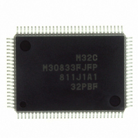
M30833FJFP#U3 Renesas Electronics America, M30833FJFP#U3 Datasheet - Page 110

M30833FJFP#U3
Manufacturer Part Number
M30833FJFP#U3
Description
IC M32C/83 MCU FLASH 100QFP
Manufacturer
Renesas Electronics America
Series
M16C™ M32C/80r
Datasheets
1.M3087BFLGPU3.pdf
(364 pages)
2.M30833FJGPU3.pdf
(96 pages)
3.M30833FJGPU3.pdf
(529 pages)
Specifications of M30833FJFP#U3
Core Processor
M32C/80
Core Size
16/32-Bit
Speed
32MHz
Connectivity
CAN, I²C, IEBus, SIO, UART/USART
Peripherals
DMA, WDT
Number Of I /o
85
Program Memory Size
512KB (512K x 8)
Program Memory Type
FLASH
Ram Size
31K x 8
Voltage - Supply (vcc/vdd)
3 V ~ 5.5 V
Data Converters
A/D 26x10b; D/A 2x8b
Oscillator Type
Internal
Operating Temperature
-40°C ~ 85°C
Package / Case
100-QFP
For Use With
R0K330879S001BE - KIT DEV RSK M32C/87R0K330879S000BE - KIT DEV RSK M32C/87
Lead Free Status / RoHS Status
Lead free / RoHS Compliant
Eeprom Size
-
Available stocks
Company
Part Number
Manufacturer
Quantity
Price
- Current page: 110 of 529
- Download datasheet (5Mb)
R
R
M
e
E
3
. v
J
Table 8.8 Pin Status in Stop Mode
2
0
NOTES:
________
Address Bus, Data Bus, CS0 to CS3, BHE
RD, WR, WRL, WRH, DW, CASL, CASH
RAS
__________
HLDA, BCLK
ALE
Port
CLK
X
X
X
_____
1
9
C
3 .
IN
OUT
CIN
B
8 /
1. When performing a self-refresh operation using DRAMC, CAS and RAS become low ("L").
2. M32C/83T cannot be used in memory expansion mode and microprocessor mode.
0
1
8.5.3.2 Exiting Stop Mode
8.5.3.3 Pin Status in Stop Mode
3
0
OUT
______
, X
Stop mode is exited by the hardware reset, NMI interrupt, or peripheral function interrupts (key input
interrupt and INT interrupt).
When the hardware reset or NMI interrupt, but not the peripheral function interrupts, is used to exit wait
mode, set all ILVL2 to ILVL0 bits in the interrupt control registers for the peripheral function interrupt to
"000
Table 8.8 lists pin status in stop mode.
3
J
G
4
• After Exiting Stop Mode
a
COUT
0 -
n
o r
(7) The oscillation stop detect function is used, set the CM20 bit in the CM2 register to "0" (oscilla
(8) Set the I flag to "1"
(9) Set the CM10 bit to "1" (all clocks stops)
Set the interrupt priority level required to exit stop mode to "7" immediately after exiting stop mode.
3 .
________
1
u
2
, 1
3
" (interrupt disabled) before setting the CM10 bit to "1" (all clocks stops).
p
1
tion stop detect function disabled)
2
When f
(
When f
M
0
_________ ______
0
3
6
2
C
Pin
______
C
8
8 /
Page 85
, f
selected
, 3
32
_______
M
selected
_________
3
2
C
f o
_______
8 /
4
3
8
________
_______
) T
8
_______
Maintains state immediately before
entering stop mode
"H"
"H"
"H"
"H"
Maintains state immediately before entering stop mode
"H"
Maintains state immediately before entering stop mode
High-impedance
"H"
High-impedance
(1)
(1)
Memory Expansion Mode
Microprocessor Mode
_______
________
(2)
________
8. Clock Generation Circuit
Single-Chip Mode
Related parts for M30833FJFP#U3
Image
Part Number
Description
Manufacturer
Datasheet
Request
R

Part Number:
Description:
KIT STARTER FOR M16C/29
Manufacturer:
Renesas Electronics America
Datasheet:

Part Number:
Description:
KIT STARTER FOR R8C/2D
Manufacturer:
Renesas Electronics America
Datasheet:

Part Number:
Description:
R0K33062P STARTER KIT
Manufacturer:
Renesas Electronics America
Datasheet:

Part Number:
Description:
KIT STARTER FOR R8C/23 E8A
Manufacturer:
Renesas Electronics America
Datasheet:

Part Number:
Description:
KIT STARTER FOR R8C/25
Manufacturer:
Renesas Electronics America
Datasheet:

Part Number:
Description:
KIT STARTER H8S2456 SHARPE DSPLY
Manufacturer:
Renesas Electronics America
Datasheet:

Part Number:
Description:
KIT STARTER FOR R8C38C
Manufacturer:
Renesas Electronics America
Datasheet:

Part Number:
Description:
KIT STARTER FOR R8C35C
Manufacturer:
Renesas Electronics America
Datasheet:

Part Number:
Description:
KIT STARTER FOR R8CL3AC+LCD APPS
Manufacturer:
Renesas Electronics America
Datasheet:

Part Number:
Description:
KIT STARTER FOR RX610
Manufacturer:
Renesas Electronics America
Datasheet:

Part Number:
Description:
KIT STARTER FOR R32C/118
Manufacturer:
Renesas Electronics America
Datasheet:

Part Number:
Description:
KIT DEV RSK-R8C/26-29
Manufacturer:
Renesas Electronics America
Datasheet:

Part Number:
Description:
KIT STARTER FOR SH7124
Manufacturer:
Renesas Electronics America
Datasheet:

Part Number:
Description:
KIT STARTER FOR H8SX/1622
Manufacturer:
Renesas Electronics America
Datasheet:

Part Number:
Description:
KIT DEV FOR SH7203
Manufacturer:
Renesas Electronics America
Datasheet:


