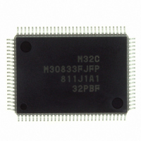
M30833FJFP#U3 Renesas Electronics America, M30833FJFP#U3 Datasheet - Page 349

M30833FJFP#U3
Manufacturer Part Number
M30833FJFP#U3
Description
IC M32C/83 MCU FLASH 100QFP
Manufacturer
Renesas Electronics America
Series
M16C™ M32C/80r
Datasheets
1.M3087BFLGPU3.pdf
(364 pages)
2.M30833FJGPU3.pdf
(96 pages)
3.M30833FJGPU3.pdf
(529 pages)
Specifications of M30833FJFP#U3
Core Processor
M32C/80
Core Size
16/32-Bit
Speed
32MHz
Connectivity
CAN, I²C, IEBus, SIO, UART/USART
Peripherals
DMA, WDT
Number Of I /o
85
Program Memory Size
512KB (512K x 8)
Program Memory Type
FLASH
Ram Size
31K x 8
Voltage - Supply (vcc/vdd)
3 V ~ 5.5 V
Data Converters
A/D 26x10b; D/A 2x8b
Oscillator Type
Internal
Operating Temperature
-40°C ~ 85°C
Package / Case
100-QFP
For Use With
R0K330879S001BE - KIT DEV RSK M32C/87R0K330879S000BE - KIT DEV RSK M32C/87
Lead Free Status / RoHS Status
Lead free / RoHS Compliant
Eeprom Size
-
Available stocks
Company
Part Number
Manufacturer
Quantity
Price
- Current page: 349 of 529
- Download datasheet (5Mb)
R
R
M
22. CAN Module
e
E
3
. v
J
NOTES:
Table 22.1 CAN Module Specifications
2
0
The CAN (Controller Area Network) module incorporated in the M32C/83 group is a Full CAN module,
compatible with CAN Specification 2.0 Part B. Table 22.1 lists specifications of the CAN module.
Protocol
Message Slots
Polarity
Acceptance Filter
Baud Rate
Remote Frame Automatic
Answering Function
Time Stamp Function
BasicCAN Mode
Transmit Abort Function
Loopback Function
Forcible Error Active
Clear Function
Figure 22.1 shows a block diagram of the CAN module. Figure 22.2 shows CANi message slot buffer (the
message slot buffer) (i=0,1) and CANi message slot (the message slot) j (j=0 to 15). Table 22.2 lists pin
settings of the CAN module.
The message slot cannot be accessed directly from the CPU. Allocate the message slot j to be used to the
message slot buffer 0 or 1. The message slot j is accessed via the message slot buffer address. The
CiSBS register selects the message slot j to be allocated. Figure 22.2 shows the 16-byte message slot
buffer and message slot.
1
C
9
1. Use an oscillator with maximum 1.58% oscillation tolerance.
3 .
B
8 /
0
1
3
0
3
J
G
4
a
0 -
o r
n
3 .
1
u
, 1
3
Item
p
1
(
2
M
0
0
3
6
2
C
8 /
Page 324
, 3
M
3
2
C
f o
8 /
4
from the CAN bus bit clock divided by 1, 2, 3 or 4.
CAN Specification 2.0 Part B
16 slots
Dominant: "L"
Recessive: "H"
Global mask: 1 mask (for message slots 0 to 13)
Local mask: 2 masks (for message slots 14 and 15 respectively)
Baud rate =
Tq clock cycle =
Tq per bit = SS + PTS +PBS1+PBS2
Message slot that receives the remote frame transmits the data frame
automatically
Time stamp function with a 16-bit counter. Count source can be selected
BasicCAN function can be used with the CANi message slots 14 and 15.
Transmit request is aborted
Frame transmitted by the CAN module is received by the same CAN module
The CAN module is forced into an error active state
3
8
) T
8
Tq:
BRP: Setting value in the C0BRP and C1BRP registers, 1-255
SS:
PTS: Propagation Time Segment; 1 to 8 Tq
PBS1: Phase Buffer Segment 1; 2 to 8 Tq
PBS2: Phase Buffer Segment 2 ; 2 to 8 Tq
Time quantum
Synchronization Segment; 1 Tq
Tq clock cycle x Tq per bit
BRP + 1
f
1
1
Specification
--- Max. 1 Mbps
22. CAN Module
Related parts for M30833FJFP#U3
Image
Part Number
Description
Manufacturer
Datasheet
Request
R

Part Number:
Description:
KIT STARTER FOR M16C/29
Manufacturer:
Renesas Electronics America
Datasheet:

Part Number:
Description:
KIT STARTER FOR R8C/2D
Manufacturer:
Renesas Electronics America
Datasheet:

Part Number:
Description:
R0K33062P STARTER KIT
Manufacturer:
Renesas Electronics America
Datasheet:

Part Number:
Description:
KIT STARTER FOR R8C/23 E8A
Manufacturer:
Renesas Electronics America
Datasheet:

Part Number:
Description:
KIT STARTER FOR R8C/25
Manufacturer:
Renesas Electronics America
Datasheet:

Part Number:
Description:
KIT STARTER H8S2456 SHARPE DSPLY
Manufacturer:
Renesas Electronics America
Datasheet:

Part Number:
Description:
KIT STARTER FOR R8C38C
Manufacturer:
Renesas Electronics America
Datasheet:

Part Number:
Description:
KIT STARTER FOR R8C35C
Manufacturer:
Renesas Electronics America
Datasheet:

Part Number:
Description:
KIT STARTER FOR R8CL3AC+LCD APPS
Manufacturer:
Renesas Electronics America
Datasheet:

Part Number:
Description:
KIT STARTER FOR RX610
Manufacturer:
Renesas Electronics America
Datasheet:

Part Number:
Description:
KIT STARTER FOR R32C/118
Manufacturer:
Renesas Electronics America
Datasheet:

Part Number:
Description:
KIT DEV RSK-R8C/26-29
Manufacturer:
Renesas Electronics America
Datasheet:

Part Number:
Description:
KIT STARTER FOR SH7124
Manufacturer:
Renesas Electronics America
Datasheet:

Part Number:
Description:
KIT STARTER FOR H8SX/1622
Manufacturer:
Renesas Electronics America
Datasheet:

Part Number:
Description:
KIT DEV FOR SH7203
Manufacturer:
Renesas Electronics America
Datasheet:


