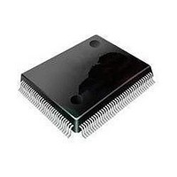
MC9S08DZ128MLL Freescale Semiconductor, MC9S08DZ128MLL Datasheet - Page 224

MC9S08DZ128MLL
Manufacturer Part Number
MC9S08DZ128MLL
Description
MCU 8BIT 128K FLASH 100-LQFP
Manufacturer
Freescale Semiconductor
Series
HCS08r
Datasheets
1.MC9S08DV96CLF.pdf
(458 pages)
2.MC9S08DV96CLF.pdf
(4 pages)
3.MC9S08DZ128CLF.pdf
(4 pages)
Specifications of MC9S08DZ128MLL
Core Processor
HCS08
Core Size
8-Bit
Speed
40MHz
Connectivity
CAN, I²C, LIN, SCI, SPI
Peripherals
LVD, POR, PWM, WDT
Number Of I /o
87
Program Memory Size
128KB (128K x 8)
Program Memory Type
FLASH
Eeprom Size
2K x 8
Ram Size
8K x 8
Voltage - Supply (vcc/vdd)
2.7 V ~ 5.5 V
Data Converters
A/D 24x12b
Oscillator Type
External
Operating Temperature
-40°C ~ 125°C
Package / Case
100-LQFP
Processor Series
S08DZ
Core
HCS08
Data Bus Width
8 bit
Data Ram Size
8 KB
Interface Type
CAN, I2C, SCI, SPI
Maximum Clock Frequency
40 MHz
Number Of Programmable I/os
88
Number Of Timers
3
Operating Supply Voltage
5.5 V
Maximum Operating Temperature
+ 125 C
Mounting Style
SMD/SMT
3rd Party Development Tools
EWS08
Development Tools By Supplier
DEMO9S08DZ60
Minimum Operating Temperature
- 40 C
On-chip Adc
12 bit, 24 Channel
Controller Family/series
HCS08
No. Of I/o's
87
Eeprom Memory Size
2KB
Ram Memory Size
8KB
Cpu Speed
40MHz
No. Of Timers
3
Digital Ic Case Style
LQFP
Rohs Compliant
Yes
Lead Free Status / RoHS Status
Lead free / RoHS Compliant
Available stocks
Company
Part Number
Manufacturer
Quantity
Price
Company:
Part Number:
MC9S08DZ128MLL
Manufacturer:
FREESCAL
Quantity:
300
Company:
Part Number:
MC9S08DZ128MLL
Manufacturer:
Freescale Semiconductor
Quantity:
10 000
- Current page: 224 of 458
- Download datasheet (5Mb)
Chapter 10 Analog-to-Digital Converter (S08ADC12V1)
When a conversion is aborted, the contents of the data registers, ADCRH and ADCRL, are not altered.
However, they continue to be the values transferred after the completion of the last successful conversion.
If the conversion was aborted by a reset, ADCRH and ADCRL return to their reset states.
10.4.4.4
The ADC module remains in its idle state until a conversion is initiated. If ADACK is selected as the
conversion clock source, the ADACK clock generator is also enabled.
Power consumption when active can be reduced by setting ADLPC. This results in a lower maximum value
for f
10.4.4.5
The total conversion time depends on the sample time (as determined by ADLSMP), the MCU bus
frequency, the conversion mode (8-bit, 10-bit or 12-bit), and the frequency of the conversion clock (
After the module becomes active, sampling of the input begins. ADLSMP selects between short (3.5
ADCK cycles) and long (23.5 ADCK cycles) sample times.When sampling is complete, the converter is
isolated from the input channel and a successive approximation algorithm is performed to determine the
digital value of the analog signal. The result of the conversion is transferred to ADCRH and ADCRL upon
completion of the conversion algorithm.
If the bus frequency is less than the f
cannot be guaranteed when short sample is enabled (ADLSMP=0). If the bus frequency is less than 1/11th
of the f
sample is enabled (ADLSMP=1).
224
The maximum total conversion time for different conditions is summarized in
ADCK
Single or first continuous 10-bit or 12-bit
Single or first continuous 10-bit or 12-bit
Single or first continuous 10-bit or 12-bit
Single or first continuous 10-bit or 12-bit
Subsequent continuous 10-bit or 12-bit;
ADCK
Single or first continuous 8-bit
Single or first continuous 8-bit
Single or first continuous 8-bit
Single or first continuous 8-bit
Subsequent continuous 8-bit;
Subsequent continuous 8-bit;
(see the electrical specifications).
frequency, precise sample time for continuous conversions cannot be guaranteed when long
Power Control
Sample Time and Total Conversion Time
Conversion Type
f
BUS
f
f
BUS
BUS
> f
> f
> f
ADCK
ADCK
ADCK
Table 10-13. Total Conversion Time vs. Control Conditions
/11
MC9S08DZ128 Series Data Sheet, Rev. 1
ADCK
frequency, precise sample time for continuous conversions
ADICLK
0x, 10
0x, 10
0x, 10
0x, 10
11
11
11
11
xx
xx
xx
ADLSMP
0
0
1
1
0
0
1
1
0
0
1
20 ADCK cycles + 5 bus clock cycles
23 ADCK cycles + 5 bus clock cycles
40 ADCK cycles + 5 bus clock cycles
43 ADCK cycles + 5 bus clock cycles
5 μs + 20 ADCK + 5 bus clock cycles
5 μs + 23 ADCK + 5 bus clock cycles
5 μs + 40 ADCK + 5 bus clock cycles
5 μs + 43 ADCK + 5 bus clock cycles
Max Total Conversion Time
17 ADCK cycles
20 ADCK cycles
37 ADCK cycles
Table
Freescale Semiconductor
10-13.
f
ADCK
).
Related parts for MC9S08DZ128MLL
Image
Part Number
Description
Manufacturer
Datasheet
Request
R
Part Number:
Description:
Manufacturer:
Freescale Semiconductor, Inc
Datasheet:
Part Number:
Description:
Manufacturer:
Freescale Semiconductor, Inc
Datasheet:
Part Number:
Description:
Manufacturer:
Freescale Semiconductor, Inc
Datasheet:
Part Number:
Description:
Manufacturer:
Freescale Semiconductor, Inc
Datasheet:
Part Number:
Description:
Manufacturer:
Freescale Semiconductor, Inc
Datasheet:
Part Number:
Description:
Manufacturer:
Freescale Semiconductor, Inc
Datasheet:
Part Number:
Description:
Manufacturer:
Freescale Semiconductor, Inc
Datasheet:
Part Number:
Description:
Manufacturer:
Freescale Semiconductor, Inc
Datasheet:
Part Number:
Description:
Manufacturer:
Freescale Semiconductor, Inc
Datasheet:
Part Number:
Description:
Manufacturer:
Freescale Semiconductor, Inc
Datasheet:
Part Number:
Description:
Manufacturer:
Freescale Semiconductor, Inc
Datasheet:
Part Number:
Description:
Manufacturer:
Freescale Semiconductor, Inc
Datasheet:
Part Number:
Description:
Manufacturer:
Freescale Semiconductor, Inc
Datasheet:
Part Number:
Description:
Manufacturer:
Freescale Semiconductor, Inc
Datasheet:
Part Number:
Description:
Manufacturer:
Freescale Semiconductor, Inc
Datasheet:


