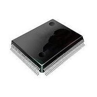
MC9S08DZ128MLL Freescale Semiconductor, MC9S08DZ128MLL Datasheet - Page 393

MC9S08DZ128MLL
Manufacturer Part Number
MC9S08DZ128MLL
Description
MCU 8BIT 128K FLASH 100-LQFP
Manufacturer
Freescale Semiconductor
Series
HCS08r
Datasheets
1.MC9S08DV96CLF.pdf
(458 pages)
2.MC9S08DV96CLF.pdf
(4 pages)
3.MC9S08DZ128CLF.pdf
(4 pages)
Specifications of MC9S08DZ128MLL
Core Processor
HCS08
Core Size
8-Bit
Speed
40MHz
Connectivity
CAN, I²C, LIN, SCI, SPI
Peripherals
LVD, POR, PWM, WDT
Number Of I /o
87
Program Memory Size
128KB (128K x 8)
Program Memory Type
FLASH
Eeprom Size
2K x 8
Ram Size
8K x 8
Voltage - Supply (vcc/vdd)
2.7 V ~ 5.5 V
Data Converters
A/D 24x12b
Oscillator Type
External
Operating Temperature
-40°C ~ 125°C
Package / Case
100-LQFP
Processor Series
S08DZ
Core
HCS08
Data Bus Width
8 bit
Data Ram Size
8 KB
Interface Type
CAN, I2C, SCI, SPI
Maximum Clock Frequency
40 MHz
Number Of Programmable I/os
88
Number Of Timers
3
Operating Supply Voltage
5.5 V
Maximum Operating Temperature
+ 125 C
Mounting Style
SMD/SMT
3rd Party Development Tools
EWS08
Development Tools By Supplier
DEMO9S08DZ60
Minimum Operating Temperature
- 40 C
On-chip Adc
12 bit, 24 Channel
Controller Family/series
HCS08
No. Of I/o's
87
Eeprom Memory Size
2KB
Ram Memory Size
8KB
Cpu Speed
40MHz
No. Of Timers
3
Digital Ic Case Style
LQFP
Rohs Compliant
Yes
Lead Free Status / RoHS Status
Lead free / RoHS Compliant
Available stocks
Company
Part Number
Manufacturer
Quantity
Price
Company:
Part Number:
MC9S08DZ128MLL
Manufacturer:
FREESCAL
Quantity:
300
Company:
Part Number:
MC9S08DZ128MLL
Manufacturer:
Freescale Semiconductor
Quantity:
10 000
- Current page: 393 of 458
- Download datasheet (5Mb)
Chapter 18
Debug Module (S08DBGV3)
18.1
The DBG module implements an on-chip ICE (in-circuit emulation) system and allows non-intrusive
debug of application software by providing an on-chip trace buffer with flexible triggering capability. The
trigger also can provide extended breakpoint capacity. The on-chip ICE system is optimized for the HCS08
8-bit architecture and supports 64K bytes or 128K bytes of memory space.
18.1.1
The on-chip ICE system includes these distinctive features:
Freescale Semiconductor
•
•
•
•
Three comparators (A, B, and C) with ability to match addresses in 128K space
— Dual mode, Comparators A and B used to compare addresses
— Full mode, Comparator A compares address and Comparator B compares data
— Can be used as triggers and/or breakpoints
— Comparator C can be used as a normal hardware breakpoint
— Loop1 capture mode, Comparator C is used to track most recent COF event captured into FIFO
Tag and Force type breakpoints
Nine trigger modes
— A
— A Or B
— A Then B
— A And B, where B is data (Full mode)
— A And Not B, where B is data (Full mode)
— Event Only B, store data
— A Then Event Only B, store data
— Inside Range, A ≤ Address ≤ B
— Outside Range, Address < Α or Address > B
FIFO for storing change of flow information and event only data
— Source address of conditional branches taken
— Destination address of indirect JMP and JSR instruction
— Destination address of interrupts, RTI, RTC, and RTS instruction
— Data associated with Event B trigger modes
Introduction
Features
MC9S08DZ128 Series Data Sheet, Rev. 1
(128K)
393
Related parts for MC9S08DZ128MLL
Image
Part Number
Description
Manufacturer
Datasheet
Request
R
Part Number:
Description:
Manufacturer:
Freescale Semiconductor, Inc
Datasheet:
Part Number:
Description:
Manufacturer:
Freescale Semiconductor, Inc
Datasheet:
Part Number:
Description:
Manufacturer:
Freescale Semiconductor, Inc
Datasheet:
Part Number:
Description:
Manufacturer:
Freescale Semiconductor, Inc
Datasheet:
Part Number:
Description:
Manufacturer:
Freescale Semiconductor, Inc
Datasheet:
Part Number:
Description:
Manufacturer:
Freescale Semiconductor, Inc
Datasheet:
Part Number:
Description:
Manufacturer:
Freescale Semiconductor, Inc
Datasheet:
Part Number:
Description:
Manufacturer:
Freescale Semiconductor, Inc
Datasheet:
Part Number:
Description:
Manufacturer:
Freescale Semiconductor, Inc
Datasheet:
Part Number:
Description:
Manufacturer:
Freescale Semiconductor, Inc
Datasheet:
Part Number:
Description:
Manufacturer:
Freescale Semiconductor, Inc
Datasheet:
Part Number:
Description:
Manufacturer:
Freescale Semiconductor, Inc
Datasheet:
Part Number:
Description:
Manufacturer:
Freescale Semiconductor, Inc
Datasheet:
Part Number:
Description:
Manufacturer:
Freescale Semiconductor, Inc
Datasheet:
Part Number:
Description:
Manufacturer:
Freescale Semiconductor, Inc
Datasheet:


