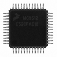
MC9S12C32CFAE16 Freescale Semiconductor, MC9S12C32CFAE16 Datasheet - Page 262

MC9S12C32CFAE16
Manufacturer Part Number
MC9S12C32CFAE16
Description
IC MCU 32K FLASH 16MHZ 48-LQFP
Manufacturer
Freescale Semiconductor
Series
HCS12r
Datasheets
1.MC9S12GC16MFUE.pdf
(690 pages)
2.MC9S12C96CFUER.pdf
(26 pages)
3.MC9S12C32CFAE25.pdf
(2 pages)
Specifications of MC9S12C32CFAE16
Core Processor
HCS12
Core Size
16-Bit
Speed
16MHz
Connectivity
CAN, EBI/EMI, SCI, SPI
Peripherals
POR, PWM, WDT
Number Of I /o
31
Program Memory Size
32KB (32K x 8)
Program Memory Type
FLASH
Ram Size
2K x 8
Voltage - Supply (vcc/vdd)
2.35 V ~ 5.5 V
Data Converters
A/D 8x10b
Oscillator Type
Internal
Operating Temperature
-40°C ~ 85°C
Package / Case
48-LQFP
Cpu Family
HCS12
Device Core Size
16b
Frequency (max)
16MHz
Interface Type
CAN/SCI/SPI
Total Internal Ram Size
2KB
# I/os (max)
31
Number Of Timers - General Purpose
8
Operating Supply Voltage (typ)
2.5/5V
Operating Supply Voltage (max)
2.75/5.5V
Operating Supply Voltage (min)
2.35/2.97V
On-chip Adc
8-chx10-bit
Instruction Set Architecture
CISC
Operating Temp Range
-40C to 85C
Operating Temperature Classification
Industrial
Mounting
Surface Mount
Pin Count
48
Package Type
LQFP
Package
48LQFP
Family Name
HCS12
Maximum Speed
16 MHz
Operating Supply Voltage
2.5|5 V
Data Bus Width
16 Bit
Number Of Programmable I/os
31
Number Of Timers
8
For Use With
CML12C32SLK - KIT STUDENT LEARNING 16BIT HCS12
Lead Free Status / RoHS Status
Lead free / RoHS Compliant
Eeprom Size
-
Lead Free Status / Rohs Status
Compliant
Available stocks
Company
Part Number
Manufacturer
Quantity
Price
Company:
Part Number:
MC9S12C32CFAE16
Manufacturer:
Freescale Semiconductor
Quantity:
10 000
- Current page: 262 of 690
- Download datasheet (4Mb)
Chapter 9 Clocks and Reset Generator (CRGV4) Block Description
9.3.2.8
This register selects the timeout period for the real-time interrupt.
Read: anytime
Write: anytime
262
Module Base + 0x0007
Reset
SCME
AUTO
Field
ACQ
PRE
PCE
5
4
2
1
0
W
R
Automatic Bandwidth Control Bit — AUTO selects either the high bandwidth (acquisition) mode or the low
bandwidth (tracking) mode depending on how close to the desired frequency the VCO is running. Write anytime
except when PLLWAI=1, because PLLWAI sets the AUTO bit to 1.
0 Automatic mode control is disabled and the PLL is under software control, using ACQ bit.
1 Automatic mode control is enabled and ACQ bit has no effect.
Acquisition Bit — Write anytime. If AUTO=1 this bit has no effect.
0 Low bandwidth filter is selected.
1 High bandwidth filter is selected.
RTI Enable during Pseudo-Stop Bit — PRE enables the RTI during pseudo-stop mode. Write anytime.
0 RTI stops running during pseudo-stop mode.
1 RTI continues running during pseudo-stop mode.
Note: If the PRE bit is cleared the RTI dividers will go static while pseudo-stop mode is active. The RTI dividers
COP Enable during Pseudo-Stop Bit — PCE enables the COP during pseudo-stop mode. Write anytime.
0 COP stops running during pseudo-stop mode
1 COP continues running during pseudo-stop mode
Note: If the PCE bit is cleared the COP dividers will go static while pseudo-stop mode is active. The COP dividers
Self-Clock Mode Enable Bit — Normal modes: Write once —Special modes: Write anytime — SCME can not
be cleared while operating in self-clock mode (SCM=1).
0 Detection of crystal clock failure causes clock monitor reset (see
1 Detection of crystal clock failure forces the MCU in self-clock mode (see
CRG RTI Control Register (RTICTL)
0
0
7
A write to this register initializes the RTI counter.
will not initialize like in wait mode with RTIWAI bit set.
will not initialize like in wait mode with COPWAI bit set.
= Unimplemented or Reserved
RTR6
0
6
Table 9-5. PLLCTL Field Descriptions (continued)
Figure 9-11. CRG RTI Control Register (RTICTL)
RTR5
MC9S12C-Family / MC9S12GC-Family
0
5
Rev 01.24
RTR4
NOTE
0
4
Description
RTR3
0
3
Section 9.5.1, “Clock Monitor
RTR2
0
2
Section 9.4.7.2, “Self-Clock
Freescale Semiconductor
RTR1
0
1
Reset”).
RTR0
Mode”).
0
0
Related parts for MC9S12C32CFAE16
Image
Part Number
Description
Manufacturer
Datasheet
Request
R
Part Number:
Description:
Manufacturer:
Freescale Semiconductor, Inc
Datasheet:
Part Number:
Description:
Manufacturer:
Freescale Semiconductor, Inc
Datasheet:
Part Number:
Description:
Manufacturer:
Freescale Semiconductor, Inc
Datasheet:
Part Number:
Description:
Manufacturer:
Freescale Semiconductor, Inc
Datasheet:
Part Number:
Description:
Manufacturer:
Freescale Semiconductor, Inc
Datasheet:
Part Number:
Description:
Manufacturer:
Freescale Semiconductor, Inc
Datasheet:
Part Number:
Description:
Manufacturer:
Freescale Semiconductor, Inc
Datasheet:
Part Number:
Description:
Manufacturer:
Freescale Semiconductor, Inc
Datasheet:
Part Number:
Description:
Manufacturer:
Freescale Semiconductor, Inc
Datasheet:
Part Number:
Description:
Manufacturer:
Freescale Semiconductor, Inc
Datasheet:
Part Number:
Description:
Manufacturer:
Freescale Semiconductor, Inc
Datasheet:
Part Number:
Description:
Manufacturer:
Freescale Semiconductor, Inc
Datasheet:
Part Number:
Description:
Manufacturer:
Freescale Semiconductor, Inc
Datasheet:
Part Number:
Description:
Manufacturer:
Freescale Semiconductor, Inc
Datasheet:
Part Number:
Description:
Manufacturer:
Freescale Semiconductor, Inc
Datasheet:


