MC9S12C32CFAE16 Freescale Semiconductor, MC9S12C32CFAE16 Datasheet - Page 268
MC9S12C32CFAE16
Manufacturer Part Number
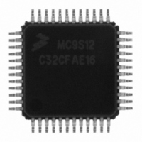
MC9S12C32CFAE16
Description
IC MCU 32K FLASH 16MHZ 48-LQFP
Manufacturer
Freescale Semiconductor
Series
HCS12r
Datasheets
1.MC9S12GC16MFUE.pdf
(690 pages)
2.MC9S12C96CFUER.pdf
(26 pages)
3.MC9S12C32CFAE25.pdf
(2 pages)
Specifications of MC9S12C32CFAE16
Core Processor
HCS12
Core Size
16-Bit
Speed
16MHz
Connectivity
CAN, EBI/EMI, SCI, SPI
Peripherals
POR, PWM, WDT
Number Of I /o
31
Program Memory Size
32KB (32K x 8)
Program Memory Type
FLASH
Ram Size
2K x 8
Voltage - Supply (vcc/vdd)
2.35 V ~ 5.5 V
Data Converters
A/D 8x10b
Oscillator Type
Internal
Operating Temperature
-40°C ~ 85°C
Package / Case
48-LQFP
Cpu Family
HCS12
Device Core Size
16b
Frequency (max)
16MHz
Interface Type
CAN/SCI/SPI
Total Internal Ram Size
2KB
# I/os (max)
31
Number Of Timers - General Purpose
8
Operating Supply Voltage (typ)
2.5/5V
Operating Supply Voltage (max)
2.75/5.5V
Operating Supply Voltage (min)
2.35/2.97V
On-chip Adc
8-chx10-bit
Instruction Set Architecture
CISC
Operating Temp Range
-40C to 85C
Operating Temperature Classification
Industrial
Mounting
Surface Mount
Pin Count
48
Package Type
LQFP
Package
48LQFP
Family Name
HCS12
Maximum Speed
16 MHz
Operating Supply Voltage
2.5|5 V
Data Bus Width
16 Bit
Number Of Programmable I/os
31
Number Of Timers
8
For Use With
CML12C32SLK - KIT STUDENT LEARNING 16BIT HCS12
Lead Free Status / RoHS Status
Lead free / RoHS Compliant
Eeprom Size
-
Lead Free Status / Rohs Status
Compliant
Available stocks
Company
Part Number
Manufacturer
Quantity
Price

Company:
Part Number:
MC9S12C32CFAE16
Manufacturer:
Freescale Semiconductor
Quantity:
10 000


Chapter 9 Clocks and Reset Generator (CRGV4) Block Description
The PLL filter can be manually or automatically configured into one of two possible operating modes:
The PLL can change the bandwidth or operational mode of the loop filter manually or automatically.
In automatic bandwidth control mode (AUTO = 1), the lock detector automatically switches between
acquisition and tracking modes. Automatic bandwidth control mode also is used to determine when the
PLL clock (PLLCLK) is safe to use as the source for the system and core clocks. If PLL LOCK interrupt
requests are enabled, the software can wait for an interrupt request and then check the LOCK bit. If CPU
interrupts are disabled, software can poll the LOCK bit continuously (during PLL start-up, usually) or at
periodic intervals. In either case, only when the LOCK bit is set, is the PLLCLK clock safe to use as the
source for the system and core clocks. If the PLL is selected as the source for the system and core clocks
and the LOCK bit is clear, the PLL has suffered a severe noise hit and the software must take appropriate
action, depending on the application.
The following conditions apply when the PLL is in automatic bandwidth control mode (AUTO = 1):
The PLL can also operate in manual mode (AUTO = 0). Manual mode is used by systems that do not
require an indicator of the lock condition for proper operation. Such systems typically operate well below
the maximum system frequency (f
manual mode:
268
•
•
•
•
•
•
•
•
•
•
Acquisition mode
In acquisition mode, the filter can make large frequency corrections to the VCO. This mode is used
at PLL start-up or when the PLL has suffered a severe noise hit and the VCO frequency is far off
the desired frequency. When in acquisition mode, the TRACK status bit is cleared in the CRGFLG
register.
Tracking mode
In tracking mode, the filter makes only small corrections to the frequency of the VCO. PLL jitter
is much lower in tracking mode, but the response to noise is also slower. The PLL enters tracking
mode when the VCO frequency is nearly correct and the TRACK bit is set in the CRGFLG register.
The TRACK bit is a read-only indicator of the mode of the filter.
The TRACK bit is set when the VCO frequency is within a certain tolerance, ∆
the VCO frequency is out of a certain tolerance, ∆
The LOCK bit is a read-only indicator of the locked state of the PLL.
The LOCK bit is set when the VCO frequency is within a certain tolerance, ∆
when the VCO frequency is out of a certain tolerance, ∆
CPU interrupts can occur if enabled (LOCKIE = 1) when the lock condition changes, toggling the
LOCK bit.
ACQ is a writable control bit that controls the mode of the filter. Before turning on the PLL in
manual mode, the ACQ bit should be asserted to configure the filter in acquisition mode.
After turning on the PLL by setting the PLLON bit software must wait a given time (t
entering tracking mode (ACQ = 0).
After entering tracking mode software must wait a given time (t
as the source for system and core clocks (PLLSEL = 1).
sys
MC9S12C-Family / MC9S12GC-Family
) and require fast start-up. The following conditions apply when in
Rev 01.24
unt
.
unl
.
al
) before selecting the PLLCLK
Freescale Semiconductor
trk
Lock
, and is clear when
, and is cleared
acq
) before
Related parts for MC9S12C32CFAE16
Image
Part Number
Description
Manufacturer
Datasheet
Request
R

Part Number:
Description:
Manufacturer:
Freescale Semiconductor, Inc
Datasheet:
Part Number:
Description:
Manufacturer:
Freescale Semiconductor, Inc
Datasheet:
Part Number:
Description:
Manufacturer:
Freescale Semiconductor, Inc
Datasheet:
Part Number:
Description:
Manufacturer:
Freescale Semiconductor, Inc
Datasheet:
Part Number:
Description:
Manufacturer:
Freescale Semiconductor, Inc
Datasheet:
Part Number:
Description:
Manufacturer:
Freescale Semiconductor, Inc
Datasheet:
Part Number:
Description:
Manufacturer:
Freescale Semiconductor, Inc
Datasheet:
Part Number:
Description:
Manufacturer:
Freescale Semiconductor, Inc
Datasheet:
Part Number:
Description:
Manufacturer:
Freescale Semiconductor, Inc
Datasheet:
Part Number:
Description:
Manufacturer:
Freescale Semiconductor, Inc
Datasheet:
Part Number:
Description:
Manufacturer:
Freescale Semiconductor, Inc
Datasheet:
Part Number:
Description:
Manufacturer:
Freescale Semiconductor, Inc
Datasheet:
Part Number:
Description:
Manufacturer:
Freescale Semiconductor, Inc
Datasheet:
Part Number:
Description:
Manufacturer:
Freescale Semiconductor, Inc
Datasheet:
Part Number:
Description:
Manufacturer:
Freescale Semiconductor, Inc
Datasheet: