DF36054GFPJV Renesas Electronics America, DF36054GFPJV Datasheet - Page 24
DF36054GFPJV
Manufacturer Part Number
DF36054GFPJV
Description
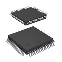
MCU 3/5V 32K J-TEMP PB-FREE 64-L
Manufacturer
Renesas Electronics America
Series
H8® H8/300H Tinyr
Datasheet
1.DF36057GFZV.pdf
(594 pages)
Specifications of DF36054GFPJV
Core Processor
H8/300H
Core Size
16-Bit
Speed
20MHz
Connectivity
CAN, SCI, SSU
Peripherals
LVD, POR, PWM, WDT
Number Of I /o
45
Program Memory Size
32KB (32K x 8)
Program Memory Type
FLASH
Ram Size
2K x 8
Voltage - Supply (vcc/vdd)
3 V ~ 5.5 V
Data Converters
A/D 8x10b
Oscillator Type
Internal
Operating Temperature
-40°C ~ 85°C
Package / Case
64-LQFP
Lead Free Status / RoHS Status
Lead free / RoHS Compliant
Eeprom Size
-


Figure 5.5 Typical Connection to Ceramic Resonator.................................................................. 75
Figure 5.6 Example of External Clock Input ................................................................................ 75
Figure 5.7 Example of Incorrect Board Design ............................................................................ 76
Section 6 Power-Down Modes
Figure 6.1 Mode Transition Diagram ........................................................................................... 82
Section 7 ROM
Figure 7.1 Flash Memory Block Configuration............................................................................ 90
Figure 7.2 Programming/Erasing Flowchart Example in User Program Mode............................ 99
Figure 7.3 Program/Program-Verify Flowchart ......................................................................... 101
Figure 7.4 Erase/Erase-Verify Flowchart ................................................................................... 104
Section 9 I/O Ports
Figure 9.1 Port 1 Pin Configuration............................................................................................ 111
Figure 9.2 Port 2 Pin Configuration............................................................................................ 116
Figure 9.3 Port 5 Pin Configuration............................................................................................ 120
Figure 9.4 Port 6 Pin Configuration............................................................................................ 126
Figure 9.5 Port 7 Pin Configuration............................................................................................ 131
Figure 9.6 Port 8 Pin Configuration............................................................................................ 135
Figure 9.7 Port 9 Pin Configuration............................................................................................ 137
Figure 9.8 Port B Pin Configuration........................................................................................... 141
Section 10 Timer B1
Figure 10.1 Block Diagram of Timer B1.................................................................................... 143
Section 11 Timer V
Figure 11.1 Block Diagram of Timer V ..................................................................................... 150
Figure 11.2 Increment Timing with Internal Clock .................................................................... 157
Figure 11.3 Increment Timing with External Clock................................................................... 157
Figure 11.4 OVF Set Timing ...................................................................................................... 157
Figure 11.5 CMFA and CMFB Set Timing................................................................................ 158
Figure 11.6 TMOV Output Timing ............................................................................................ 158
Figure 11.7 Clear Timing by Compare Match............................................................................ 158
Figure 11.8 Clear Timing by TMRIV Input ............................................................................... 159
Figure 11.9 Pulse Output Example ............................................................................................. 159
Figure 11.10 Example of Pulse Output Synchronized to TRGV Input....................................... 160
Figure 11.11 Contention between TCNTV Write and Clear ...................................................... 161
Figure 11.12 Contention between TCORA Write and Compare Match ..................................... 162
Figure 11.13 Internal Clock Switching and TCNTV Operation ................................................. 162
Rev. 4.00 Mar. 15, 2006 Page xxii of xxxii
Related parts for DF36054GFPJV
Image
Part Number
Description
Manufacturer
Datasheet
Request
R

Part Number:
Description:
KIT STARTER FOR M16C/29
Manufacturer:
Renesas Electronics America
Datasheet:

Part Number:
Description:
KIT STARTER FOR R8C/2D
Manufacturer:
Renesas Electronics America
Datasheet:

Part Number:
Description:
R0K33062P STARTER KIT
Manufacturer:
Renesas Electronics America
Datasheet:

Part Number:
Description:
KIT STARTER FOR R8C/23 E8A
Manufacturer:
Renesas Electronics America
Datasheet:

Part Number:
Description:
KIT STARTER FOR R8C/25
Manufacturer:
Renesas Electronics America
Datasheet:

Part Number:
Description:
KIT STARTER H8S2456 SHARPE DSPLY
Manufacturer:
Renesas Electronics America
Datasheet:

Part Number:
Description:
KIT STARTER FOR R8C38C
Manufacturer:
Renesas Electronics America
Datasheet:

Part Number:
Description:
KIT STARTER FOR R8C35C
Manufacturer:
Renesas Electronics America
Datasheet:

Part Number:
Description:
KIT STARTER FOR R8CL3AC+LCD APPS
Manufacturer:
Renesas Electronics America
Datasheet:
Part Number:
Description:
KIT STARTER FOR RX610
Manufacturer:
Renesas Electronics America
Datasheet:

Part Number:
Description:
KIT STARTER FOR R32C/118
Manufacturer:
Renesas Electronics America
Datasheet:

Part Number:
Description:
KIT DEV RSK-R8C/26-29
Manufacturer:
Renesas Electronics America
Datasheet:

Part Number:
Description:
KIT STARTER FOR SH7124
Manufacturer:
Renesas Electronics America
Datasheet:

Part Number:
Description:
KIT STARTER FOR H8SX/1622
Manufacturer:
Renesas Electronics America
Datasheet:

Part Number:
Description:
KIT DEV FOR SH7203
Manufacturer:
Renesas Electronics America
Datasheet: