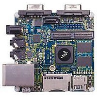
MCIMX53-START Freescale Semiconductor, MCIMX53-START Datasheet - Page 120

MCIMX53-START
Manufacturer Part Number
MCIMX53-START
Description
KIT DEVELOPMENT I.MX53
Manufacturer
Freescale Semiconductor
Series
i.MX53r
Type
MCUr
Datasheets
1.MCIMX53-START.pdf
(2 pages)
2.MCIMX53-START.pdf
(180 pages)
3.MCIMX53-START.pdf
(204 pages)
Specifications of MCIMX53-START
Contents
Board
Silicon Manufacturer
Freescale
Core Architecture
ARM
Core Sub-architecture
Cortex - A8
Silicon Core Number
I.MX5
Silicon Family Name
I.MX53
Peak Reflow Compatible (260 C)
Yes
Rohs Compliant
Yes
Leaded Process Compatible
Yes
Lead Free Status / RoHS Status
Lead free / RoHS Compliant
For Use With/related Products
i.MX53
Lead Free Status / Rohs Status
Supplier Unconfirmed
Available stocks
Company
Part Number
Manufacturer
Quantity
Price
- Current page: 120 of 180
- Download datasheet (2Mb)
Electrical Characteristics
4.7.13.2 Ultra DMA (UDMA) Input Timing
Figure 72
host terminates transfer,
Table 74
120
1
2
Parameter
tk1 in the MDMA figures
tk1 in the MDMA figures equals (tk – 2*T).
ATA
tn, tj
—
lists the timing parameters for UDMA in burst.
shows timing when the UDMA in transfer starts,
Figure 70
Figure 71
Parameter from
tkjn
ton
toff
i.MX53xA Automotive and Infotainment Applications Processors, Rev. 1
Table 73. MDMA Read and Write Timing Parameters (continued)
(Read),
(Write)
(Figure 70
Figure 74
Figure 72. UDMA in Transfer Starts Timing Diagram
tn= tj= tkjn = time_jn * T – (tskew1 + tskew2 + tskew6)
ton = time_on
toff = time_off
and
shows timing when the UDMA in device terminates transfer, and
Figure
×
×
71) equals (tk – 2*T).
T – tskew1
T – tskew1
Value
Figure 73
shows timing when the UDMA in
Freescale Semiconductor
Controlling
Variable
time_jn
—
Related parts for MCIMX53-START
Image
Part Number
Description
Manufacturer
Datasheet
Request
R
Part Number:
Description:
MCIMX-LVDS1
Manufacturer:
Freescale Semiconductor
Datasheet:
Part Number:
Description:
Manufacturer:
Freescale Semiconductor, Inc
Datasheet:
Part Number:
Description:
Manufacturer:
Freescale Semiconductor, Inc
Datasheet:
Part Number:
Description:
Manufacturer:
Freescale Semiconductor, Inc
Datasheet:
Part Number:
Description:
Manufacturer:
Freescale Semiconductor, Inc
Datasheet:
Part Number:
Description:
Manufacturer:
Freescale Semiconductor, Inc
Datasheet:
Part Number:
Description:
Manufacturer:
Freescale Semiconductor, Inc
Datasheet:
Part Number:
Description:
Manufacturer:
Freescale Semiconductor, Inc
Datasheet:
Part Number:
Description:
Manufacturer:
Freescale Semiconductor, Inc
Datasheet:
Part Number:
Description:
Manufacturer:
Freescale Semiconductor, Inc
Datasheet:
Part Number:
Description:
Manufacturer:
Freescale Semiconductor, Inc
Datasheet:
Part Number:
Description:
Manufacturer:
Freescale Semiconductor, Inc
Datasheet:
Part Number:
Description:
Manufacturer:
Freescale Semiconductor, Inc
Datasheet:
Part Number:
Description:
Manufacturer:
Freescale Semiconductor, Inc
Datasheet:
Part Number:
Description:
Manufacturer:
Freescale Semiconductor, Inc
Datasheet:


