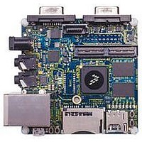
MCIMX53-START Freescale Semiconductor, MCIMX53-START Datasheet - Page 77

MCIMX53-START
Manufacturer Part Number
MCIMX53-START
Description
KIT DEVELOPMENT I.MX53
Manufacturer
Freescale Semiconductor
Series
i.MX53r
Type
MCUr
Datasheets
1.MCIMX53-START.pdf
(2 pages)
2.MCIMX53-START.pdf
(180 pages)
3.MCIMX53-START.pdf
(204 pages)
Specifications of MCIMX53-START
Contents
Board
Silicon Manufacturer
Freescale
Core Architecture
ARM
Core Sub-architecture
Cortex - A8
Silicon Core Number
I.MX5
Silicon Family Name
I.MX53
Peak Reflow Compatible (260 C)
Yes
Rohs Compliant
Yes
Leaded Process Compatible
Yes
Lead Free Status / RoHS Status
Lead free / RoHS Compliant
For Use With/related Products
i.MX53
Lead Free Status / Rohs Status
Supplier Unconfirmed
Available stocks
Company
Part Number
Manufacturer
Quantity
Price
- Current page: 77 of 180
- Download datasheet (2Mb)
4.7.5.5
In RMII mode, FEC_TX_CLK is used as the REF_CLK which is a 50 MHz ±50 ppm continuous reference
clock. FEC_RX_DV is used as the CRS_DV in RMII, and other signals under RMII mode include
FEC_TX_EN, FEC_TXD[1:0], FEC_RXD[1:0] and optional FEC_RX_ER.
The RMII mode timings are shown in
Freescale Semiconductor
1
M13 FEC_MDIO (input) to FEC_MDC rising edge hold
M14 FEC_MDC pulse width high
M15 FEC_MDC pulse width low
ID
Test conditions: 25pF on each output signal.
M16
M17
M18
M19
No.
FEC_MDIO (output)
FEC_MDC (output)
FEC_MDIO (input)
RMII Mode Timing
REF_CLK(FEC_TX_CLK) pulse width high
REF_CLK(FEC_TX_CLK) pulse width low
REF_CLK to FEC_TXD[1:0], FEC_TX_EN invalid
REF_CLK to FEC_TXD[1:0], FEC_TX_EN valid
i.MX53xA Automotive and Infotainment Applications Processors, Rev. 1
Figure 39. MII Serial Management Channel Timing Diagram
Table 51. MII Transmit Signal Timing (continued)
Characteristics
Characteristics
Table 52
Table 52. RMII Signal Timing
M12
1
and
M13
1
Figure
M14
40.
35%
35%
M10
Min
—
2
M11
M15
65%
65%
Max
16
—
Min Max
40
40
%
%
0
Electrical Characteristics
REF_CLK period
REF_CLK period
ns
ns
60% FEC_MDC period
60% FEC_MDC period
—
Unit
Unit
ns
77
Related parts for MCIMX53-START
Image
Part Number
Description
Manufacturer
Datasheet
Request
R
Part Number:
Description:
MCIMX-LVDS1
Manufacturer:
Freescale Semiconductor
Datasheet:
Part Number:
Description:
Manufacturer:
Freescale Semiconductor, Inc
Datasheet:
Part Number:
Description:
Manufacturer:
Freescale Semiconductor, Inc
Datasheet:
Part Number:
Description:
Manufacturer:
Freescale Semiconductor, Inc
Datasheet:
Part Number:
Description:
Manufacturer:
Freescale Semiconductor, Inc
Datasheet:
Part Number:
Description:
Manufacturer:
Freescale Semiconductor, Inc
Datasheet:
Part Number:
Description:
Manufacturer:
Freescale Semiconductor, Inc
Datasheet:
Part Number:
Description:
Manufacturer:
Freescale Semiconductor, Inc
Datasheet:
Part Number:
Description:
Manufacturer:
Freescale Semiconductor, Inc
Datasheet:
Part Number:
Description:
Manufacturer:
Freescale Semiconductor, Inc
Datasheet:
Part Number:
Description:
Manufacturer:
Freescale Semiconductor, Inc
Datasheet:
Part Number:
Description:
Manufacturer:
Freescale Semiconductor, Inc
Datasheet:
Part Number:
Description:
Manufacturer:
Freescale Semiconductor, Inc
Datasheet:
Part Number:
Description:
Manufacturer:
Freescale Semiconductor, Inc
Datasheet:
Part Number:
Description:
Manufacturer:
Freescale Semiconductor, Inc
Datasheet:


