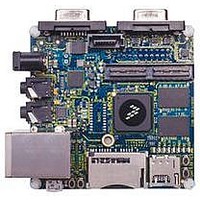
MCIMX53-START Freescale Semiconductor, MCIMX53-START Datasheet - Page 18

MCIMX53-START
Manufacturer Part Number
MCIMX53-START
Description
KIT DEVELOPMENT I.MX53
Manufacturer
Freescale Semiconductor
Series
i.MX53r
Type
MCUr
Datasheets
1.MCIMX53-START.pdf
(2 pages)
2.MCIMX53-START.pdf
(180 pages)
3.MCIMX53-START.pdf
(204 pages)
Specifications of MCIMX53-START
Contents
Board
Silicon Manufacturer
Freescale
Core Architecture
ARM
Core Sub-architecture
Cortex - A8
Silicon Core Number
I.MX5
Silicon Family Name
I.MX53
Peak Reflow Compatible (260 C)
Yes
Rohs Compliant
Yes
Leaded Process Compatible
Yes
Lead Free Status / RoHS Status
Lead free / RoHS Compliant
For Use With/related Products
i.MX53
Lead Free Status / Rohs Status
Supplier Unconfirmed
Available stocks
Company
Part Number
Manufacturer
Quantity
Price
- Current page: 18 of 180
- Download datasheet (2Mb)
Electrical Characteristics
4.1.1
18
1
2
Peripheral Core Supply Voltage
ARM Core Supply Voltage
Supply Voltage UHVIO
Supply Voltage for non UHVIO
USB VBUS
Input voltage on USB_OTG_DP, USB_OTG_DN,
USB_H1_DP, USB_H1_DN pins
Input/Output Voltage Range
ESD Damage Immunity:
Storage Temperature Range
Absolute Maximum Ratings
Package Thermal Resistance Data
i.MX53xA Operating Ranges
External Clock Sources
Maximal Supply Currents
USB Interface Current Consumption
USB_DN and USB_DP can tolerate 5 V for up to 24 hours.
The term OVDD in this section refers to the associated supply rail of an input or output. The association is described in
Table 112 on page
Absolute Maximum Ratings
Parameter Description
Stresses beyond those listed under
the device. These are stress ratings only. Functional operation of the device
at these or any other conditions beyond those indicated under
implied. Exposure to absolute-maximum-rated conditions for extended
periods may affect device reliability.
159. The maximum range can be superseded by the DC tables.
Charge Device Model (CDM)
Human Body Model (HBM)
i.MX53xA Automotive and Infotainment Applications Processors, Rev. 1
For these characteristics, …
Table 3. i.MX53xA Chip-Level Conditions
Table 4. Absolute Maximum Ratings
Supplies denoted as I/O Supply
Supplies denoted as I/O Supply
CAUTION
Table 4
USB_DP/USB_DN
T
Symbol
VDDGP
V
STORAGE
VBUS
VCC
in
V
may cause permanent damage to
/V
esd
out
Table 6
–0.3
–0.3
–0.5
–0.5
–0.3
–0.5
Min
–40
—
—
—
Table 4 on page 18
Table 5 on page 19
Table 6 on page 19
Table 7 on page 22
Table 8 on page 22
Table 9 on page 24
Topic appears …
Freescale Semiconductor
is not
OVDD +0.3
3.63
2000
Max
1.35
1.35
5.25
500
150
3.6
3.3
1
2
Unit
o
V
V
V
V
V
V
V
V
C
Related parts for MCIMX53-START
Image
Part Number
Description
Manufacturer
Datasheet
Request
R
Part Number:
Description:
MCIMX-LVDS1
Manufacturer:
Freescale Semiconductor
Datasheet:
Part Number:
Description:
Manufacturer:
Freescale Semiconductor, Inc
Datasheet:
Part Number:
Description:
Manufacturer:
Freescale Semiconductor, Inc
Datasheet:
Part Number:
Description:
Manufacturer:
Freescale Semiconductor, Inc
Datasheet:
Part Number:
Description:
Manufacturer:
Freescale Semiconductor, Inc
Datasheet:
Part Number:
Description:
Manufacturer:
Freescale Semiconductor, Inc
Datasheet:
Part Number:
Description:
Manufacturer:
Freescale Semiconductor, Inc
Datasheet:
Part Number:
Description:
Manufacturer:
Freescale Semiconductor, Inc
Datasheet:
Part Number:
Description:
Manufacturer:
Freescale Semiconductor, Inc
Datasheet:
Part Number:
Description:
Manufacturer:
Freescale Semiconductor, Inc
Datasheet:
Part Number:
Description:
Manufacturer:
Freescale Semiconductor, Inc
Datasheet:
Part Number:
Description:
Manufacturer:
Freescale Semiconductor, Inc
Datasheet:
Part Number:
Description:
Manufacturer:
Freescale Semiconductor, Inc
Datasheet:
Part Number:
Description:
Manufacturer:
Freescale Semiconductor, Inc
Datasheet:
Part Number:
Description:
Manufacturer:
Freescale Semiconductor, Inc
Datasheet:


