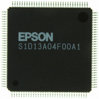
S1D13A04F00A Epson Electronics America Inc-Semiconductor Div, S1D13A04F00A Datasheet - Page 250

S1D13A04F00A
Manufacturer Part Number
S1D13A04F00A
Description
IC LCD COMPANION 160KB 128-TQFP
Manufacturer
Epson Electronics America Inc-Semiconductor Div
Specifications of S1D13A04F00A
Display Type
LCD
Voltage - Supply
1.8 V ~ 2.75 V
Mounting Type
Surface Mount
Package / Case
125-TQFP, 125-VQFP
Lead Free Status / RoHS Status
Lead free / RoHS Compliant
Current - Supply
-
Operating Temperature
-
Interface
-
Configuration
-
Digits Or Characters
-
Other names
S1D13A04F00A100
S1D13A04F00A100
S1D13A04F00A100
Available stocks
Company
Part Number
Manufacturer
Quantity
Price
Company:
Part Number:
S1D13A04F00A
Manufacturer:
Epson Electronics America Inc-Semiconductor Div
Quantity:
10 000
Company:
Part Number:
S1D13A04F00A1
Manufacturer:
EPSON
Quantity:
816
Part Number:
S1D13A04F00A1
Manufacturer:
EPSON/爱普生
Quantity:
20 000
Company:
Part Number:
S1D13A04F00A100
Manufacturer:
OSRAM
Quantity:
4 600
- Current page: 250 of 598
- Download datasheet (6Mb)
Page 78
9.2.6 Move BitBLT in Negative Direction with ROP
S1D13A04
X37A-G-003-05
Note
8. Program the BitBLT Destination/Source Linear Select bits for a rectangular BitBLT
The Move BitBLT in Negative Direction with ROP is similar to the Move BitBLT in
Positive direction. Use this BitBLT operation when the source and destination BitBLT
areas overlap and the destination address is greater then the source address. Refer to Figure
9-1: on page 76 to see when to make the decision to switch to the Move BitBLT in a
Positive direction.
When using the Move BitBLT in Negative Direction it is necessary to calculate the
addresses of the last pixels as opposed to the first pixels. This means calculating the
addresses of the lower right corners as opposed to the upper left corners.
Example 13: Copy a 9 x 101 rectangle at the screen coordinates x = 100, y = 10 to
In the following example, the coordinates of the source and destination rectangles inten-
tionally overlap.
1. Calculate the source and destination addresses (lower right corners of the source and
The sequence of register setup is irrelevant as long as all required registers are pro-
grammed before the BitBLT is started.
(BitBLT Destination Linear Select = 0, BitBLT Source Linear Select = 0).
Start the BitBLT operation. REG[8000h] bit 0 is set to 1.
destination rectangles) using the following formula.
Program the BitBLT Source Start Address Register. REG[800Ch] is set to 113D8h.
Program the BitBLT Destination Start Address Register. REG[8010h] is set to
12CE2h.
screen coordinates X = 105, Y = 20 using a 320x240 display at a color
depth of 16 bpp.
SourceAddress
DestinationAddress
where:
BytesPerPixel = 1 for 8 bpp
BytesPerPixel = 2 for 16 bpp
ScreenStride = DisplayWidthInPixels
= ((y + Height - 1)
= ((10 + 101 - 1)
= 70616
= 113D8h
= ((Y + Height - 1) ScreenStride) + ((X + Width - 1) BytesPerPixel)
= ((20 + 101 - 1)
= 77026
= 12CE2h
(320
(320
ScreenStride) + ((x + Width - 1)
2)) + ((100 + 9 - 1)
2)) + ((105 + 9 - 1)
BytesPerPixel = 640 for 16 bpp
Epson Research and Development
Programming Notes and Examples
2)
2)
Vancouver Design Center
Issue Date: 2002/08/21
BytesPerPixel)
Related parts for S1D13A04F00A
Image
Part Number
Description
Manufacturer
Datasheet
Request
R

Part Number:
Description:
IC CONTROLLER CRT/LCD/TV 128-QFP
Manufacturer:
Epson Electronics America Inc-Semiconductor Div
Part Number:
Description:
IC GRAPHIC LCD CTRLR 256-PBGA
Manufacturer:
Epson Electronics America Inc-Semiconductor Div
Datasheet:
Part Number:
Description:
MEMORY CARD 2M STATIC RAM
Manufacturer:
Epson Electronics America Inc-Semiconductor Div
Part Number:
Description:
IC CTRLR/PHY USB OTG 64-QFP
Manufacturer:
Epson Electronics America Inc-Semiconductor Div
Part Number:
Description:
IC CONTROLLER USB 2.0 64-QFP
Manufacturer:
Epson Electronics America Inc-Semiconductor Div

Part Number:
Description:
IC PHY CONT 2PORT 1394A 100-QFP
Manufacturer:
Epson Electronics America Inc-Semiconductor Div
Part Number:
Description:
IC LINK CTRLR 1394 IDE-33 184QFP
Manufacturer:
Epson Electronics America Inc-Semiconductor Div
Part Number:
Description:
IC LINK CTRLR 1394 IDE-66 184QFP
Manufacturer:
Epson Electronics America Inc-Semiconductor Div

Part Number:
Description:
IC LINK CTRLR 1394 IDE100 100QFP
Manufacturer:
Epson Electronics America Inc-Semiconductor Div

Part Number:
Description:
IC LINK CTRLR/PHY 1394 100-QFP
Manufacturer:
Epson Electronics America Inc-Semiconductor Div
Part Number:
Description:
IC CTRLR/PHY USB 2.0 64-QFP
Manufacturer:
Epson Electronics America Inc-Semiconductor Div

Part Number:
Description:
IC CTRLR/PHY USB 2.0 100-QFP
Manufacturer:
Epson Electronics America Inc-Semiconductor Div
Part Number:
Description:
IC CHARGE CTRLR LI-ION 24-SSOP
Manufacturer:
Epson Electronics America Inc-Semiconductor Div
Part Number:
Description:
IC BATTERY LEAK PREVENTION SOT89
Manufacturer:
Epson Electronics America Inc-Semiconductor Div
Part Number:
Description:
IC BATTERY LEAK PREVENTION SOT89
Manufacturer:
Epson Electronics America Inc-Semiconductor Div


